Remote control – Extron Electronics FOXBOX Tx_Rx DVI Plus User Guide User Manual
Page 25
Remote Control
This section describes the remote control operation of the FOXBOX VGA,
FOXBOX VGA/YUV, FOXBOX DVI Plus, and FOXBOX DVI, including:
•
Simple Instruction Set Control
•
The transmitter and receiver each have a Configuration port, a 2.5 mm mini stereo jack
that can be connected to a host device such as a computer running the HyperTerminal
utility, an RS-232 capable PDA, or a control system. These ports make serial control of the
transmitter and receiver possible.
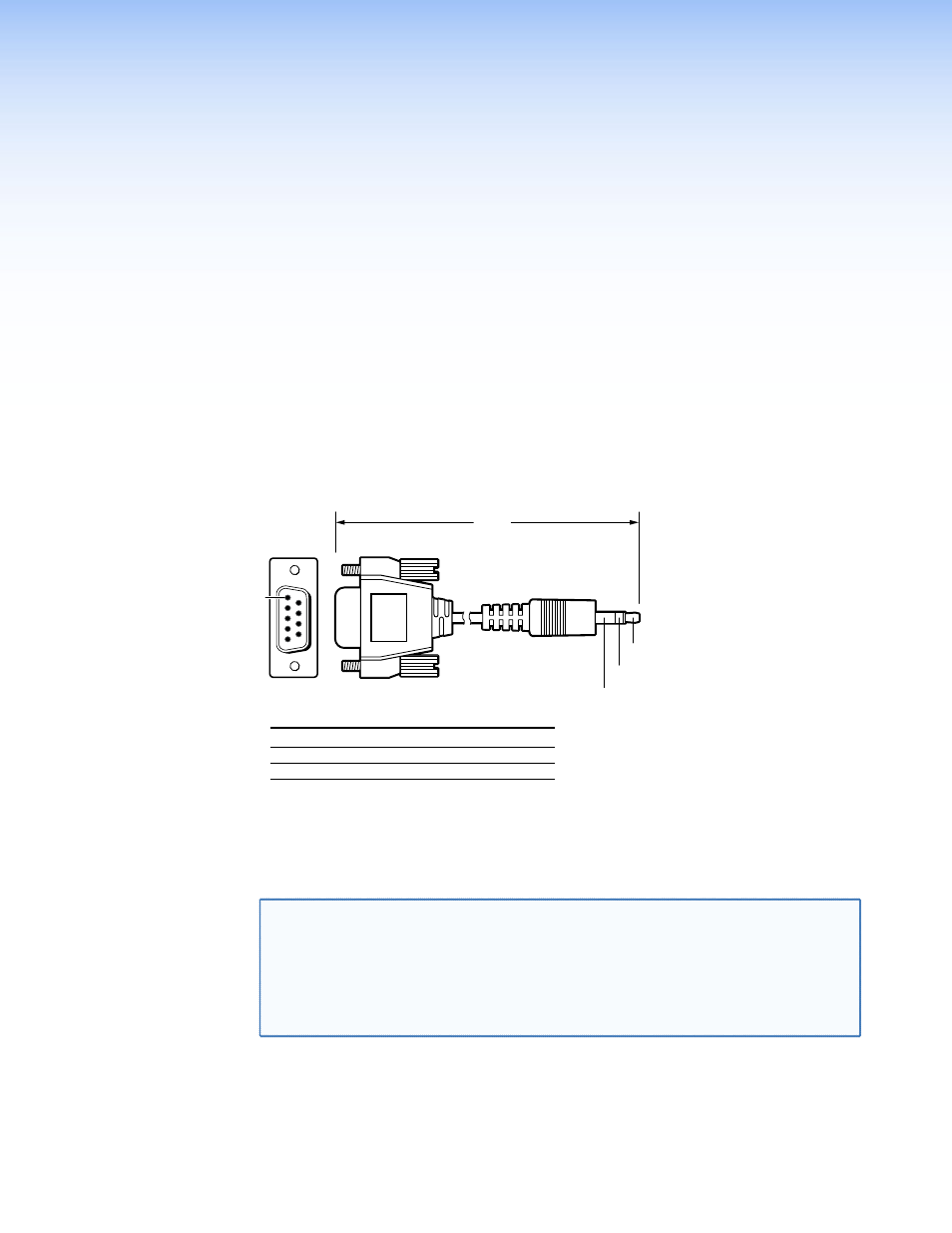
The Extron 9-pin D to 2.5 mm mini jack TRS RS-232 cable, included with the transmitter,
but available separately, part #70-335-01 (figure 12) can be used for connection to the
Configuration port.
6 feet
(1.8 m)
Part #70-335-01
5
1
9
6
Sleeve (Gnd)
Ring
Tip
9-pin D
Connection
TRS Plug
Pin 2
Computer's RX line
Tip
Pin 3
Computer's TX line
Ring
Pin 5
Computer's signal ground
Sleeve
Figure 12.
9-pin TRS RS-232 Cable
The protocol for the ports is as follows:
•
9600 baud
• no parity
• 8 data bits
•
1 stop bit
• no flow control
NOTES: Only one fiber optic cable, transmitter-Tx-to-receiver-Rx, is required for
video, audio, and serial command transmission. But, if you connect only one
fiber optic cable, you will not receive RS-232 reports from the controlled
device, and there will be reduced RS-232 command and control program
functionality on the Rx unit. To receive responses from the controlled device
and for full functionality, install both fiber optic cables and leave the FOXBOX
receiver in normal configuration (Mode DIP switch 1 down on the receiver).
FOXBOX Tx/Rx • Remote Control
19