Receiver connections and indicators, Figure 4. foxbox rx receiver connectors – Extron Electronics FOXBOX Tx_Rx DVI Plus User Guide User Manual
Page 17
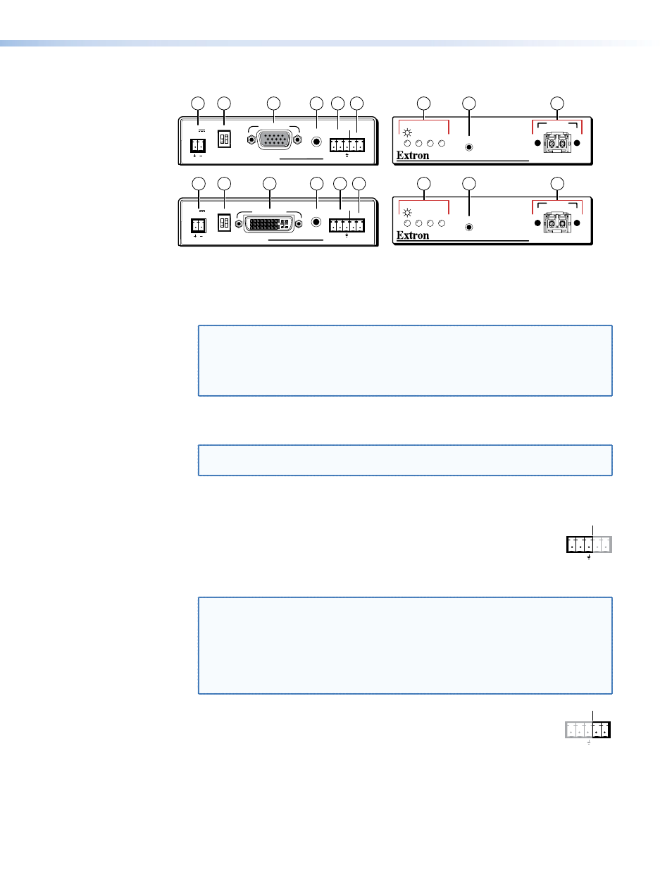
Receiver Connections and Indicators
FOXBOX Rx VGA Rear Panel
FOXBOX Rx DVI Plus Rear Panel
Front Panel
Front Panel
DVI
OVER
TEMP
AUDIO
CONFIG
OPTICAL
Rx
Tx
LINK
LINK
AUDIO
DVI-D OUTPUT
RS-232
OVER FIBER ALARM
Tx Rx
1 2
12V
1.0A MAX
POWER
MODE
FOXBOX Rx VGA
RGB
OVER
TEMP
AUDIO
CONFIG
OPTICAL
Rx
Tx
LINK
LINK
AUDIO
RGB OUTPUT
FOXBOX Rx VGA
RS-232
OVER FIBER ALARM
Tx Rx
1 2
12V
1.0A MAX
POWER
MODE
FOXBOX Rx DVI Plus
FOXBOX Rx DVI Plus
17
17
14
14
13
13
12
10
12
16
16
18
18
11
9
15
15
9
19
19
Figure 4.
FOXBOX Rx Receiver Connectors
j
RGB Output connector (FOXBOX Rx VGA only) — Connect an analog VGA-UXGA
RGB or YUV video display to this 15-pin HD female connector.
NOTE: If the transmitter input is RGB video, you can set the receiver to output the
desired video format: RGBHV or RGsB video.
If the input to a FOXBOX Tx VGA/YUV is component video, the output of
the receiver is YUV video only. Neither unit can convert the video into the
RGB format.
k
DVI-I Output connector (FOXBOX DVI only) — Connect a DVI video display to this
DVI-I connector (see “
“ on page 14 for pin assignments.
NOTE: The FOXBOX DVI outputs only the digital signals on the DVI-I Output
connector. The analog pins on the port are not connected.
l
Audio connector — Plug an audio device into this stereo mini jack connector. See
on page 8 for wiring.
m
RS-232 Over Fiber port — If you want the FOXBOX to pass serial
ALARM
Tx Rx
1 2
RS-232
OVER FIBER
command signals to the receiver, for serial control of a projector for example,
connect the host device to the transmitter via the first three leftmost poles
(Tx, Rx, and
_
) of this 5-pole captive screw connector (see “
“ on page 15 to wire this connector.
NOTES: • If you connect only one fiber optic cable (
you configure the receiver for daisy-chaining, you will not receive reports
from the controlled device. To receive responses from the controlled
device, you must install two fiber optic cables and leave the FOXBOX
receiver in normal configuration (Mode DIP switch 1 down).
• The FOXBOX can pass RS-232 commands and responses at rates up to
115200 baud.
n
Alarm outputs port — For remote monitoring of the status of fiber optic
ALARM
Tx Rx
1 2
RS-232
OVER FIBER
link 1, connect a locally-constructed or furnished monitoring device to the
receiver via the two rightmost poles (1 and 2) of this 5-pole captive screw
connector. When the receiver does not detect a light link on fiber cable Tx,
pin 1 and pin 2 of this port are shorted together.
FOXBOX Tx/Rx • Installation and Operation
11