Edid lock – Extron Electronics DVI DA Plus Series User Guide User Manual
Page 16
EDID Lock
Some applications require the distribution amplifier to maintain specific EDID information.
This information could be lost after power is cycled off and on or when a new output display
is connected to the DVI DA Plus.
By default the EDID Lock mode DIP switch is set to “Off”. In this position, when the
distribution amplifier is powered off, the EDID information that was being used is erased.
When the distribution amplifier is powered back on, it automatically scans all detectable
outputs, selects the device with the lowest native resolution and passes the EDID information
from that device to the input device. If no output devices are detected, the distribution
amplifier uses the factory default EDID (1024x768 @ 60 Hz).
While the distribution amplifier remains powered on, it monitors the Hot Plug Detect (HPD)
signal on each output and repeats the scan process whenever a display is connected or
disconnected.
When EDID Lock feature is enabled, the last recorded EDID is saved to the input and used
when the power is cycled on and off or when a new display, with a different resolution, is
connected.
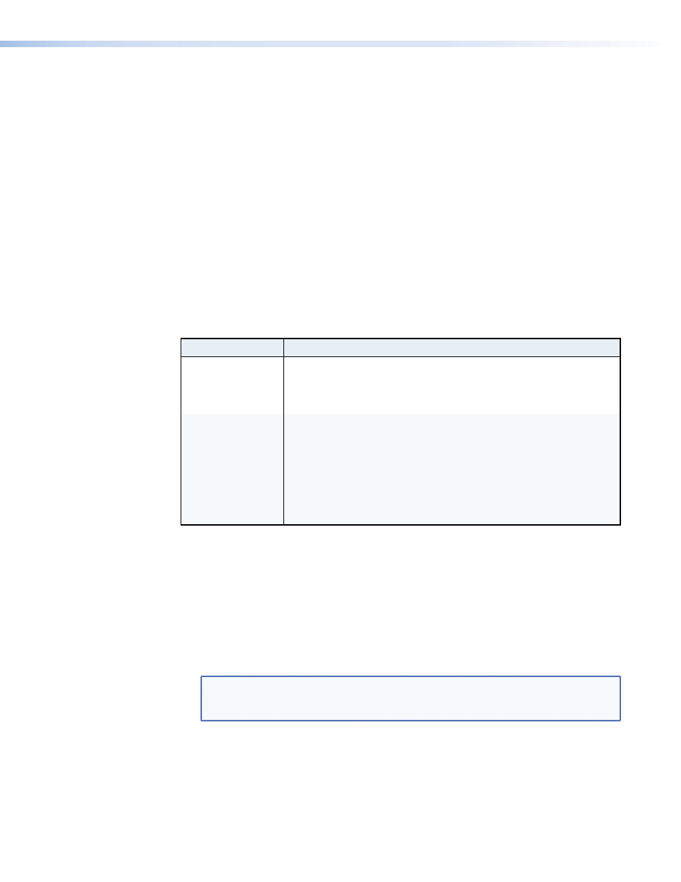
Switch Position Action on the Input
On (Lock)
• The last recorded EDID is stored to the input.
• After a power cycle, the stored EDID is used.
• After changing the displays connected to the DA, the
stored EDID is used.
Off (Default)
• After a power cycle, the DA reads EDID from all valid
displays, determines the lowest resolution, and stores
that to the input.
• After changing displays, the DA reads EDID from all valid
displays, determines the lowest resolution, and stores
that to the input.
• When no displays are connected, the factory default
EDID (1024x768 @ 60 Hz) is provided to the input.
To enable the EDID Lock feature:
1.
Remove and keep the screws holding the cover to the base. For the DVI DA4 Plus, there
are three screws along the rear edge of the top and two screws on each side. For the
DVI DA6 Plus and DVI DA8 Plus, there are four screws along the rear edge of the top
and three screws along each side. Set aside the cover.
2.
Check the part number of the printed circuit board (see figure 5). The boards must have
a part number of 20-1667-01LF and higher for the DVI DA4 Plus or 20-1683-02LF and
higher for the DVI DA6 Plus or DVI DA8 Plus.
NOTE: If the part number of the board is lower than these values, the EDID Lock
feature is not available on your model. Replace the cover as described in
step 5.
3.
Locate the Pre-emphasis and EDID Lock DIP switches. Figure 5, shows the switches for
the DVI DA4 Plus. The DVI DA6 Plus and DVI DA8 Plus have an identical block of DIP
switches in a similar position on the circuit board. The EDID Lock DIP switch (number 2)
is labeled EDID Mode.
DVI DA Plus Series • Operation
10