Dvi connector pin assignments – Extron Electronics DVI DA Plus Series User Guide User Manual
Page 12
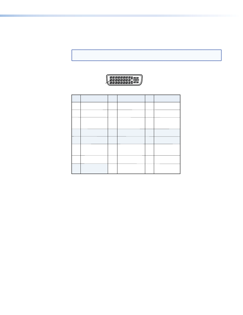
DVI Connector Pin Assignments
The illustration below shows the pin assignments for the DVI-I connectors. See the note
under input connectors for information about DVI signal compatibility.
NOTE: The DVI DA Plus series distribution amplifiers are not High-Bandwidth Digital
Content Protection (HDCP) compliant.
Pin
Signal
1
TMDS data 2–
TMDS data 2+
TMDS data 1–
TMDS data 1+
DDC clock
+5 V power
DDC data
TMDS clock+
Ground
TMDS clock–
Hotplug detect
TMDS data 0–
TMDS data 0+
Spare
Spare
Spare
Spare
Spare
Spare
TMDS data
2/4 shield
TMDS data
1/3 shield
TMDS data
0/5 shield
TMDS clock
shield
Pin
Pin
Signal
Signal
2
9
10
17
4
12
20
5
13
21
6
14
22
7
15
23
8
16
24
18
3
11
19
DVI - Female
1
9
8
17
24
Spare
DVI DA Plus Series • Installation
6
See also other documents in the category Extron Electronics Accessories for video:
- FOX Matrix 3200 (132 pages)
- ADA 2-4-6 Series (3 pages)
- ADA 6 Component (2 pages)
- AVT 100 (37 pages)
- AVT 200HD Setup Guide (4 pages)
- AVT 200HD User Guide (118 pages)
- AVTrac (482) User Guide (28 pages)
- CAT 5 Receivers (15 pages)
- CAT 5 Transmitters (15 pages)
- CD 400 (3 pages)
- CD 800 (15 pages)
- CD 900 (19 pages)
- CD 100 (18 pages)
- CSVEQ 100 D (2 pages)
- CSVEQ 100 D (38 pages)
- DA RGB_YUV Series (17 pages)
- CVEQ1, CVEQ1 WM, CVEQ1 AAP (17 pages)
- CVEQ_SVEQ 100 Series Setup Guide (2 pages)
- CVDA 6 EQ MX (3 pages)
- CVDA 6 EQ MX (2 pages)
- CVC 300 (8 pages)
- CVC 200 (4 pages)
- CVC 100 (2 pages)
- DDS 402 (54 pages)
- DDS 100 (54 pages)
- DA AV EQ Series (2 pages)
- DVC 501 SD User Guide (38 pages)
- DVC 501 SD Setup Guide (2 pages)
- DTP T USW 333 User Guide (26 pages)
- DTP T USW 333 Setup Guide (4 pages)
- DTP T USW 233 User Guide (26 pages)
- DTP T USW 233 Setup Guide (4 pages)
- DTP HDMI 330 User Guide (19 pages)
- DTP HDMI 330 Setup Guide (2 pages)
- DTP HDMI 301 User Guide (23 pages)
- DTP HDMI 301 Setup Guide (2 pages)
- DTP HDMI 230 User Guide (19 pages)
- DTP HDMI 230 Setup Guide (2 pages)
- DTP HDMI 230 D User Guide (22 pages)
- DTP DVI 330 User Guide (19 pages)
- DTP DVI 330 Setup Guide (2 pages)
- DTP DVI 301 User Guide (23 pages)
- DTP DVI 301 Setup Guide (2 pages)
- DTP DVI 230 User Guide (19 pages)
- DTP DVI 230 Setup Guide (2 pages)