Extron Electronics DVI DA Plus Series User Guide User Manual
Page 15
3.
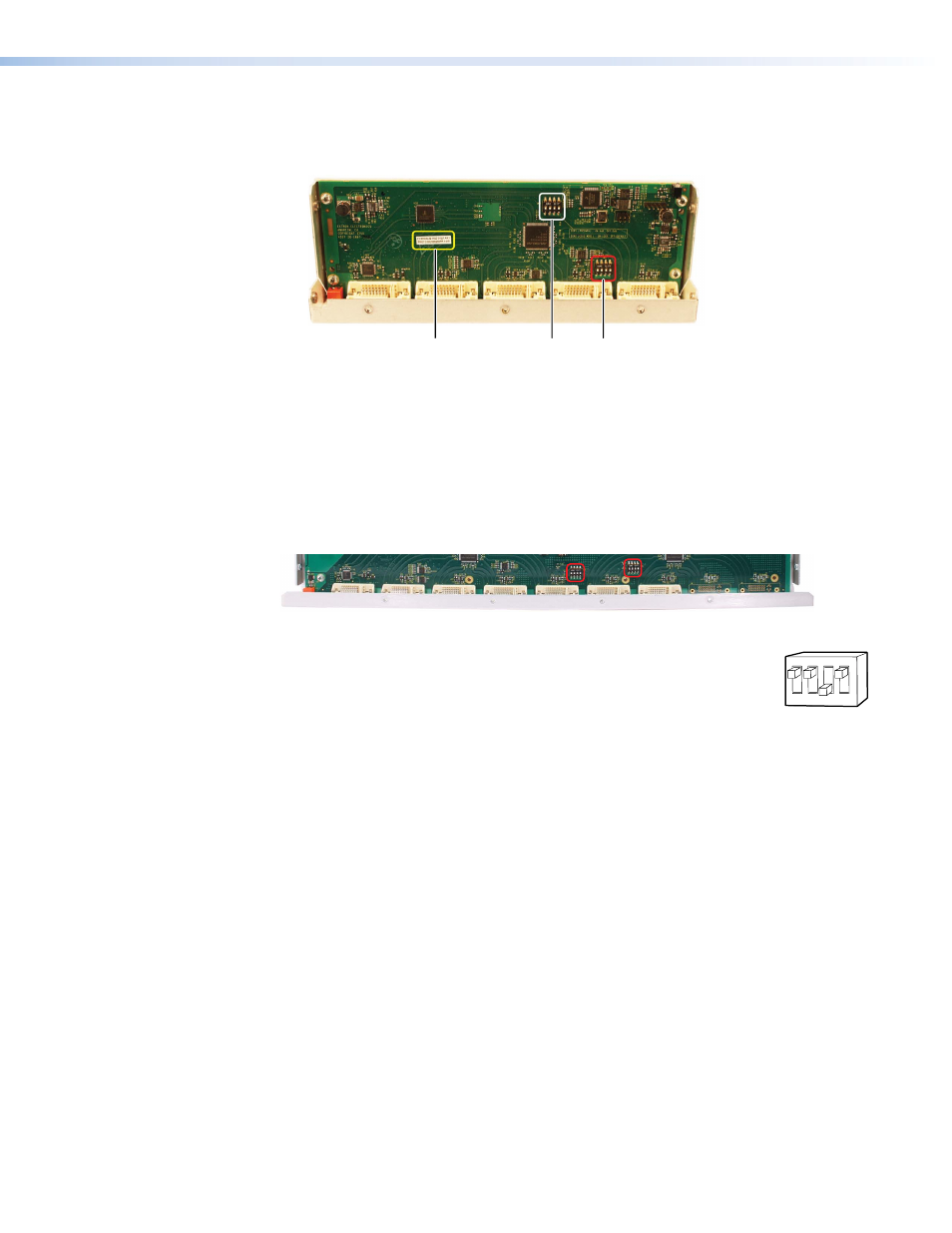
Locate the DIP switches. There is a single bank of four switches for the DVI DA4 Plus
(outlined in red in figure 5). Each switch regulates the correspondingly numbered output
(1-4).
Part Number
EDID Minder
Inactivation
DIP Switches
EDID Lock and
Pre-emphasis
DIP Switches
Rear Panel
Figure 5.
Printed Circuit Board for the DVI DA4 Plus
There are two banks of four switches for the DVI DA6 Plus (see figure 6) and the
DVI DA8 Plus. In the bank to the left, each switch regulates the correspondingly
numbered output (1-4). In the bank to the right, switches 1 and 2 correspond to
outputs 5 and 6 for the DVI DA6 Plus; switches 1-4 correspond to outputs 5-8 for the
DVI DA8 Plus.
EDID Disable DIP Switches
Bank 1:
Outputs 1-4
Bank 2:
Outputs 5-6 (DVI DA6 Plus)
Outputs 5-8 (DVI DA8 Plus)
Figure 6.
EDID Disable DIP Switches for the DVI DA6 Plus
4.
By default the switches are in the “Off” (down) position, allowing
the EDID information to be read from the corresponding output. To
deactivate EDID Minder for one or more outputs, move the switch for
that output to the “On” (up) position. In the diagram at right, the unit
will read EDID from output 3, but not from outputs 1, 2, or 4.
5.
Replace the cover, using the screws that were removed in step 1.
3
4
1
2
ON CIT
DVI DA Plus Series • Operation
9