Rear panel features, Installation and connection, cont’d – Extron Electronics AVT 100 User Manual
Page 9
Installation and Connection, cont’d
AVT 100 • Installation and Connection
AVT 100 • Installation and Connection
Ridges
Smooth
Power Supply
Output Cord
SECTION A–A
A
A
Ridges
Smooth
2-Pole Orange
Captive Screw Connector (12V)
Tie Wrap
3/16”
(5 mm) Max.
Power connector wiring
2
Radio frequency (RF) connector
— Plug an antenna or CATV
cable into the 75 ohm F type female coaxial connector (for
NTSC), or into the 75 ohm female IEC 169-2 connector (for PAL).
3
Cable/antenna switch
— Use this DIP switch to select between
cable (CATV) and antenna (TV) modes. Presets and NTSC
Auto-Scan channels are saved separately for antenna and CATV.
4
Composite video output connector
— Plug a television or other
A/V output device into this female BNC connector.
5
Audio connector
— Plug an audio output device into this 5-pole
captive screw connector. Balanced or unbalanced audio is
output on this connector.
Tip
Ring
Tip
Ring
Tip
Sleeve(s)
Tip
Unbalanced
Stereo Output
NO GROUND HERE.
NO GROUND HERE.
Balanced
Stereo Output
3/16” (5 mm)
max.
Do not tin
the wires!
Wiring the audio output connector
2-5
2-4
Rear Panel Features
The following figure shows the switches and connectors on the
rear panel of the AVT 100.
C
US
POWER
12V
0.5A MAX
L R
RS-232 / IR
Tx Rx
IR +12
VID
RF
CABLE
RE
S
ER
VED
ANT
ANT IN
OUTPUT
NTSC
AUDIO
7
8
6
2
3
4
5
1
AVT 100 rear panel
1
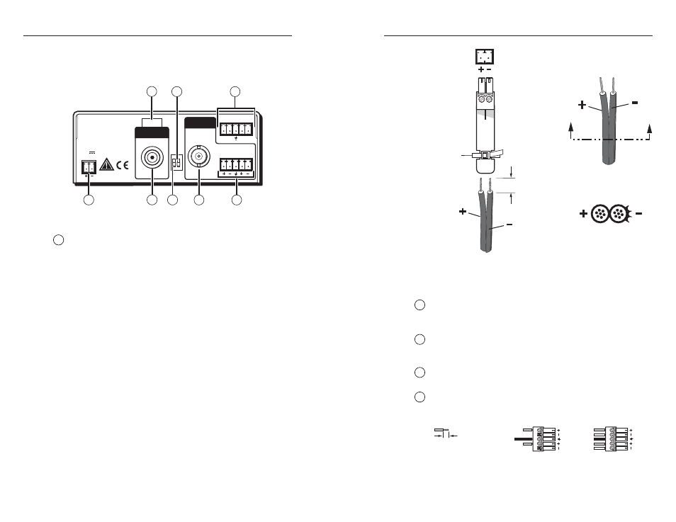
Power connector
— Plug the external 12 VDC power supply
into this 2-pin, 3.5 mm captive screw connector. The power
supply is included with the unit. The figure on the next page
shows how to wire the connector.
C
The length of the exposed (stripped) copper wires is
important. The ideal length is 3/16" (5 mm).
Longer bare wires can short together. Shorter wires
are not as secure in the captive screw connectors
and could be pulled out.
C
Do not tin the stripped power supply leads before
installing the captive screw connector. Tinned
wires are not as secure in the captive screw
connectors and could be pulled out.
W
Keep the two power cord wires separate while
plugging in the power supply. Remove power
before wiring.
To verify the polarity before connection, plug in the power
supply with no load and check the output with a voltmeter.