Ch. 3: operation, Chapter three, Operation – Extron Electronics AVT 100 User Manual
Page 12: Avt 100, Installation and connection, cont’d
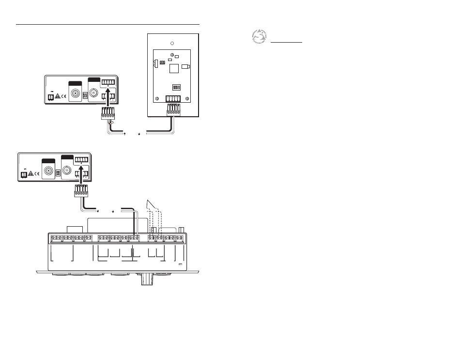
Installation and Connection, cont’d
AVT 100 • Installation and Connection
AVT 100
3
Chapter Three
Operation
Front Panel Features
Using the Control Buttons
Special Functions
Using the IR Remote Control for AVT 100
2-10
POWER
12V
0.5A MAX
L R
RS-232 / IR
Tx Rx
IR +12
VID
RF
CABLE
RE
S
ER
VED
ANT
ANT IN
OUTPUT
Modulated IR
1K Resistor
Ground ( )
D
B
IR
AVT 100 Rear Panel
MLC 52
Rear Panel
Wiring the AVT 100 to an MLC 52
POWER
12V
0.5A MAX
L R
RS-232 / IR
Tx Rx
IR +12
VID
RF
CABLE
RE
S
ER
VED
ANT
ANT IN
OUTPUT
Modulated IR
Ground ( )
D
B
IR
AVT 100 Rear Panel
Here
or here
MLC 226 IP Bottom Panel
A B C D E
DISPLAY
RS-232/IR
RS-232 12V
CM/IR/SCP
A B C D E
MLS PWR
A B
Tx/IR
Rx
GR
OUND
PWR
S
N
S
GR
OUND
+12V OUT
Rx
Tx
GR
OUND
GR
OUND
+12V IN
+12V OUT
GR
OUND
CONT MOD
IR IN
S
CP COM
NORMALLY OPEN
1 2
COMMON
COMMON
COMMON
GR
OUND
Tx/IR
Tx/IR
Tx/IR
GR
OUND
GR
OUND
A
RELAYS
IR/SERIAL OUT
3 4
B
5 6
C
A
B
C
Wiring the AVT 100 to an MLC 226 IP
N
The MLC can also control the AVT 100 via an optional
IR Emitter. Refer to your MLC user’s manual for
information on connecting the emitter.