Connecting the avt 100 to a medialink™ controller, Installation and connection, cont’d, Connecting the avt 100 to a medialink – Extron Electronics AVT 100 User Manual
Page 11: Controller, Signal, Mute
Installation and Connection, cont’d
AVT 100 • Installation and Connection
AVT 100 • Installation and Connection
2-8
5
.
Plug the other end of the cable into the RS-232/IR port on
the rear panel of the AVT 100.
C
Do not connect more than one IR Link (either in
parallel or in series) to a demodulator.
POWER
12V
0.5A MAX
L R
RS-232 / IR
Tx Rx
IR +12
VID
RF
CABLE
RE
S
ER
VED
ANT
ANT IN
OUTPUT
AUDIO
AVT 100 Rear Panel
IR Link
AVT 100 Remote
SIGNAL
IR LINK
Channel
TV TUNE
A
VT 100 REMO
TE
PRESET
Video Audio
0 1
2
3
4 5
6
7
8 9
ENTER
SA
VE
150' (45 m) maximum
MUTE
Using the AVT 100 IR Remote with the IR Link
The following diagram shows how to wire the AVT 100 to use
the infrared remote control with the optional IR Link.
POWER
12V
0.5A MAX
L R
RS-232 / IR
Tx Rx
IR +12
VID
RF
CABLE
RE
S
ER
VED
ANT
ANT IN
OUTPUT
Modulated IR
+12 VDC
Ground ( )
D
B
A
IR
12
AVT 100 Rear Panel
IR Link Rear Panel
AVT 100 Remote
Channel
TV
TUNE
A
VT 100 REMO
TE
PRESET
Video
Audio
01
2
3
45
6
7
89
E
N
T
E
R
S
A
V
E
MUTE
Wiring the IR Link to the AVT 100
N
The ground pin is shared between RS-232 control and
the IR Link connection.
2-9
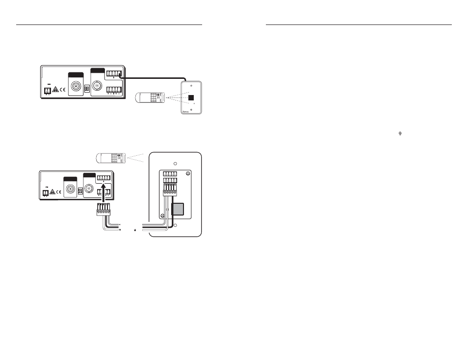
Connecting the AVT 100 to a MediaLink
™
Controller
You can hard wire an MLC MediaLink
™
Controller’s modulated
IR output connector directly to the AVT 100 to provide remote
control of the AVT.
Follow these steps to connect the AVT 100 to an MLC. See the
diagrams on the next page for examples.
1
.
Cut a length of 150' (45 m) or less of Extron Comm-Link
(CTL or CTLP) cable, which will go between the AVT 100
and the MediaLink controller.
2
.
Attach the provided 3.5 mm, 5-pole connector to the end of
the cable that will attach to the AVT 100, connecting one
wire to the center pin (which will plug into the AVT’s
ground connector pin, marked with ), and another wire
to the pin to the right of the center ground pin. (This pin
will plug into the AVT’s IR connector.) Plug this end of the
cable into the RS-232/IR connector on the AVT’s rear
panel.
3
.
On the other (MediaLink controller) end of the cable, do
either of the following:
•
Attach the cable’s corresponding wires to the ground
and IR output pins of the captive screw connector
that will plug into the MLC. Plug this end of the
cable into the IR connector on the MLC’s rear panel.
•
Attach the cable’s wires directly to the ground and IR
output pins on the MLC’s rear panel.
4
.
Using Global Configurator software, program the MLC
with the proper IR drivers for the AVT 100. Refer to your
MediaLink controller user’s manual for more information.
N
If the AVT 100 does not respond to commands from the
MediaLink controller, a 1k ohm resistor may be required
between the ground and IR pins on the AVT 100.
This resistor is required when you are using an MLC 52
to control the AVT.