Setup and commissioning – Bell & Gossett P2001489 Integrated Technologic with Sensorless Control User Manual
Page 31
Setup and commissioning
WARNING:
System commissioning must be performed by qualified personnel.
• Ensure that all piping connections are made before commissioning the drive.
• Follow all start-up procedures for the motor, pump, and controller as indicated in their
respective manuals.
• Refer to the Technologic controller IOM for detailed information on controller
programming and parameters.
• Some default parameters are configured specially for the Integrated Sensorless
controller. The default parameters that are listed in the Technologic controller IOM
may be different.
• The motor parameters have been configured at the factory for the motor provided
with the Integrated Technologic Controller. Do not modify the motor parameters.
Modification of the motor parameters can result in malfunction of the sensorless
control algorithm.
Sensorless operation
This product has been equipped with sensorless control capability. This feature allows
control of a process variable (pressure or flow) without the need of installing an external
transducer. Sensorless control is intended for use in closed loop systems such as hydronic
circulating pump systems. Sensorless control is not intended for open loop systems. The
sensorless control method uses the relationship between head (pressure), flow, power
and speed (frequency) to determine the appropriate speed for the pump that is required
to maintain the process variable setpoint. Since these relationships change with the use of
different pumps and motors, pump performance data for the pump used must be
programmed in to the controller. This data has been pre-programmed in to the drive at
the factory to give the most accurate control possible. The controller is pre-configured at
the factory for sensorless pressure control (Set-up 3).
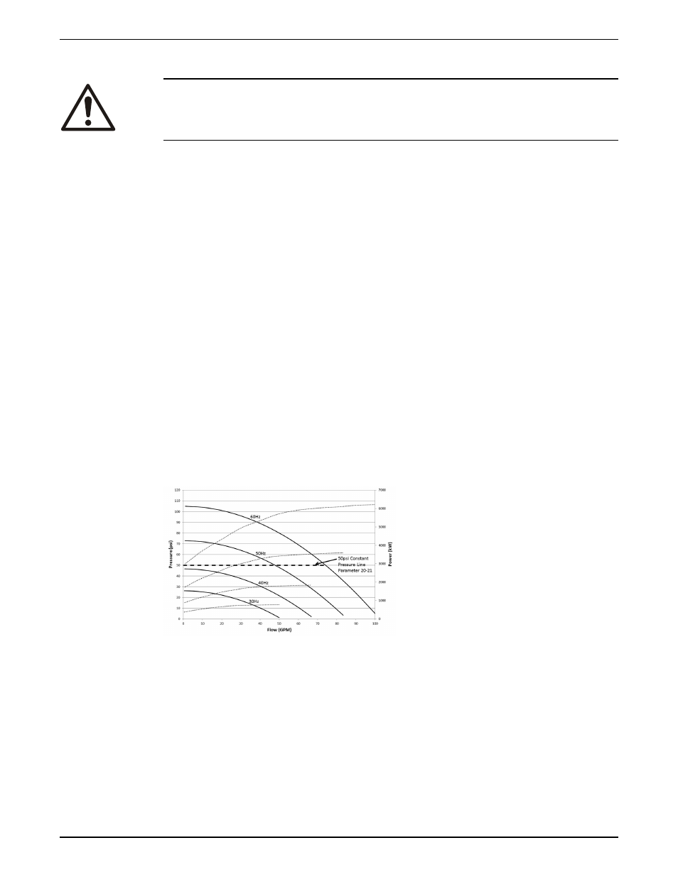
Figure 15: Pump performance and power curves
The solid lines in the diagram above show typical pump performance curves at various
speeds. The dotted lines show the pump power curve at various speeds. The dashed line
shows the setpoint of the process variable, in this case pressure. If a wired pressure
transducer was used, the transducer would provide feedback to the pressure control
loop. The pressure control loop would then calculate the speed required to maintain the
setpoint during various flow conditions. In the case of sensorless pressure control, the
drive calculates the pressure in the system based on the speed and power consumption
of the pump and sends this value to the pressure control loop. The pressure control loop
then calculates the speed command as with the wired transducer.
In either sensorless pressure or flow control mode the manipulated variable can be
monitored or displayed by accessing parameter 18-50 Sensorless Readout [Unit]. In
System Setup and Operation
Integrated Technologic
®
with Sensorless Control INSTRUCTION MANUAL
29