Bell & Gossett P2001489 Integrated Technologic with Sensorless Control User Manual
Page 32
sensorless pressure control mode, the manipulated variable is flow (flow varies while the
pressure setpoint is maintained). In sensorless flow control mode, the manipulated
variable is pressure. The units for the manipulated variable are set in parameter 20-60
Sensorless Unit. For sensorless pressure control (Set-up 3) Sensorless Unit is set to GPM.
For sensorless flow control (Set-up 4), Sensorless Unit is set to psi.
To change to sensorless flow control, change the active set-up to Set-up 4 by changing
parameter 0-10 Active Set-up to Set-up 4.
Flow compensation
As flow in a pumping system increases, the system friction head losses will also increase.
Friction head loss is higher in systems with increased pipe lengths or decreased pipe size.
The impact of this head loss is that the pressure at different points in the system will vary
depending on flow rate and the distance from the pump. The loss will be most significant
in the zones farthest from the pump. The controller’s internal flow compensation function
is used to correct the effect of friction head loss in the system. The flow compensation
function calculates a control curve based on pump and system parameters. The controller
actively adjusts the setpoint along the control curve based on the speed of the pump. In a
pump system, change in speed is proportional to a change in flow so the controller
effectively adjusts the setpoint based on a change in speed. A change in pressure varies
with the square of the change in speed or flow so a quadratic compensation factor is used
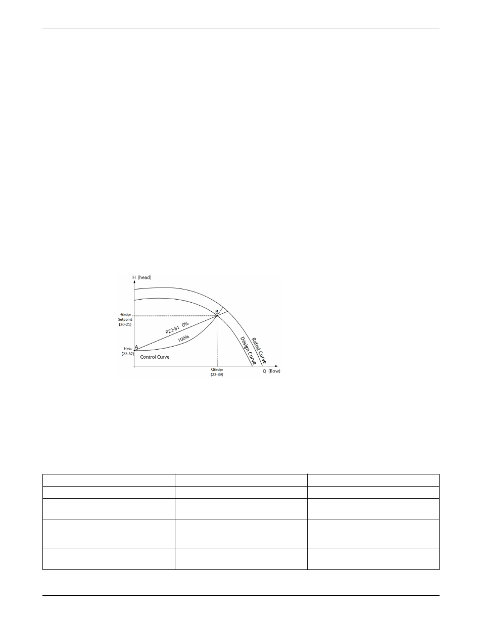
to adjust the setpoint. This is the ideal compensation curve. When the controller is
configured for sensorless pressure operation, the Square-linear curve approximation
(Parameter 22-81) is automatically configured. Parameter 22-81 can be modified to adjust
the control curve between a linear (0%) and quadratic (100%) response if a wired sensor is
used for feedback. The diagram below illustrates this concept.
Figure 16: Flow compensation with sensorless control enabled
The flow compensation function requires some system parameters to be set in the
controller to accurately model the control curve. Some parameters must be set based on
the design of the system in order to properly configure this function. Set the parameters in
the table below to properly configure the flow compensation function when the controller
is configured for sensorless control.
Table 10: Flow compensation parameters with sensorless control enabled
Parameter number
Description
Set to
22–80
Flow compensation
Enabled
22–81
Square-Linear-Curve approximation
Modify between 100% (square) and 0%
(linear) per system requirements.
22–87
Pressure at no flow
System pressure at no flow and no flow speed.
This is the minimum design head for the
system.
22–89
Flow at design point
System flow at H
Design
(pressure setpoint (20–
21))
System Setup and Operation
30
Integrated Technologic
®
with Sensorless Control INSTRUCTION MANUAL