Bell & Gossett P2001489 Integrated Technologic with Sensorless Control User Manual
Page 15
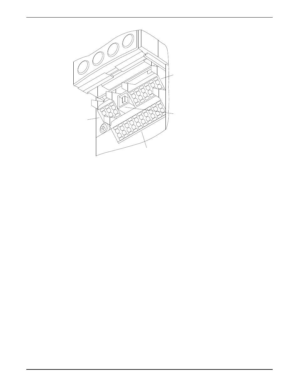
Removable control terminal connectors
1
4
2
3
130BA012.12
61
68
69
39
42
50
53
54
55
12
13
18
19
27
29
32
33
20
Figure 3: Drive control terminals
Connector 1
Digital Input and Output terminals
• Four programmable digital outputs
• Two digital terminals programmable as input or output
• A common for optional customer supplied 24 VDC voltage
• A 24 VDC supply used for digital inputs and external transducers.
Connector 2
For serial communications EIA-485 connector with terminal 68 (+) and 69
(-).
Connector 3
Analog Input and Output Terminals
• Two analog inputs configurable as current or voltage inputs
• One analog output
• A 10 VDC supply for voltage output transducers
• A common for analog inputs and outputs
Connector 4
A USB port available for use with the MCT-10 drive programming
software.
Relay Terminals Also provided are two Form C relay outputs that are in various locations
depending upon the controller configuration and size.
Connecting to the control terminals
1. To connect control wiring to the control terminals, do the following:
a. Strip the control wire back 9–10mm (0.35–0.40 in)
b. Insert a screwdriver (0.4 x 2.5 mm) in the rectangular hole.
c. Insert the cable in the adjacent circular hole.
d. Remove the screwdriver. The wire is now mounted to the terminal.
2. To remove the wire from the terminal:
a. Insert a screwdriver (0.4 x 2.5 mm) in the rectangular hole.
b. Pull out the cable.
Electrical Installation
Integrated Technologic
®
with Sensorless Control INSTRUCTION MANUAL
13