Common terminal wiring configurations – Bell & Gossett P2001489 Integrated Technologic with Sensorless Control User Manual
Page 18
Common terminal wiring configurations
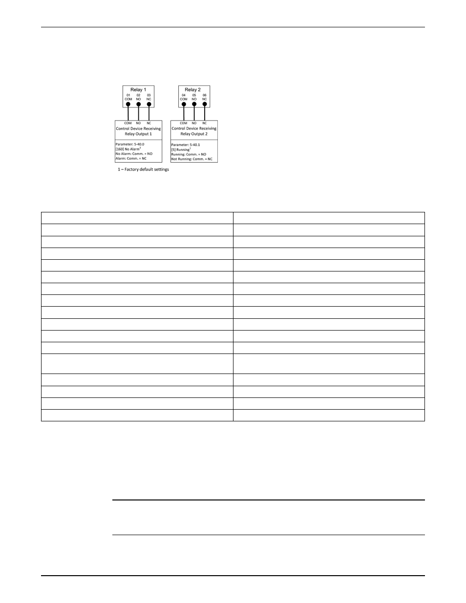
Relay wiring
Each controller has two programmable form C relay outputs. The relay terminals are
located in various locations on the controller depending on the frame size.
Figure 6: Relay terminal wiring
Table 2: Relay terminal ratings
Programmable relay outputs
2
Relay 01 Terminal number
1–3 (break), 1–2 (make)
Maximum terminal load (AC-1)
1
on 1–3 (NC), 1–2 (NO) (Resistive load) 240 V AC, 2A
Maximum terminal load (AC-15)
1
(Inductive load @ cosφ 0.4)
240 V AC, 0.2A
Maximum terminal load (DC-1)
1
on 1–2 (NO), 1–3 (NC) (Resistive load) 60 V DC, 1A
Maximum terminal load (DC-13)
1
(Inductive load)
24 V DC, 0.1A
Relay 02 Terminal number
4–6 (break), 4–5 (make)
Maximum terminal load (AC-2)
1
on 4–5 (NO) (resistive load)
2,3
400 V AC, 2A
Maximum terminal load (AC-15)
1
(Inductive load @ cosφ 0.4)
240 V AC, 0.2A
Maximum terminal load (DC-1)
1
on 4–5 (NO) (Resistive load)
80 V DC, 2A
Maximum terminal load (DC-13)
1
on 4–5 (NO) (Inductive load)
24 V DC, 0.1A
Maximum terminal load (AC-1)
1
on 4–6 (NC) (Resistive load)
240 V AC, 2A
Maximum terminal load (AC-15)
1
on 4–6 (NC) (Inductive load @ cosφ
0.4)
240 V AC, 0.2A
Maximum terminal load (DC-1)
1
on 4–6 (NC) (Resistive load)
50 V DC, 2A
Maximum terminal load (DC-13)
1
on 4–6 (NC) (Inductive load)
24 V DC, 0.1A
Minimum terminal load on 1–3 (NC), 1–2 (NO), 4–6 (NC), 4–5 (NO)
24 V DC 10mA, 24 V AC 20mA
Environment according to EN 60664–1
overvoltage category III/pollution degree 2
Factory default setup
This configuration utilizes the controller factory default settings for I/O. The factory default
settings are configured for Set-up 3, sensorless pressure control with no external
transducer installed. There are no parameters that need to be adjusted to use this
configuration. Set-up 4, sensorless flow control, also uses these default settings for I/O.
Set-ups are changed by adjusting parameter 0-10 Active Set-up. Refer to the
Commissioning section in this manual for details on changing set-ups.
NOTICE:
The factory default settings are configured to require a start signal wired to DI18 as shown
below.
Electrical Installation
16
Integrated Technologic
®
with Sensorless Control INSTRUCTION MANUAL