Control terminal configurations – Bell & Gossett P2001489 Integrated Technologic with Sensorless Control User Manual
Page 17
Control terminal configurations
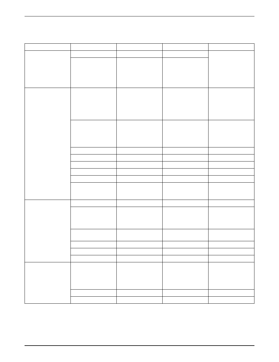
Table 1: Control terminal descriptions
Terminal number
Parameter
Default setting
Description
Relay Outputs
01, 02, 03
5-40 Relay1
[160] No Alarm
Form C Relay Output.
Usable for AC or DC
voltages and either
resistive or inductive loads.
Refer to the relay wiring
section for relay contact
current and voltage ratings.
04, 05, 06
5-40 Relay2
[5] Running
Digital I/O
12, 13
-
+24 V DC
24 V DC supply voltage.
Maximum output current is
200 mA total for all 24 V
loads. Useable for digital
inputs and external
transducers.
18
5-10
[8] Start
Start/Stop digital input
signal for the drive.
Connect input to 24 V to
start. Open the input to
stop.
19
5-11
[0] No Operation
Unused digital input
27
5-12
[0] No Operation
Unused digital input
29
5-13
[0] No Operation
Unused digital input
32
5-14
[0] No Operation
Unused digital input
33
5-15
[0] No Operation
Unused digital input
20
-
Common
Common for digital inputs
and reference for 24 V
supply
Analog I/O
39
-
AO Common
Common for analog output
42
6-50
4-20mA Motor Freq
Analog output. Default
setting is 4-20mA signal
(500 Ω max) based on
motor speed
50
-
+10 V DC
10 V DC analog supply
voltage. 15mA maximum.
53
6-1
[0] No Operation
Analog input 53.
54
6-2
[0] No Operation
Analog input 54.
55
-
AI Common
Common for analog input
Common
61
-
Shield Connection
Integrated RC filter for
cable shield. ONLY for
connecting the shield
when experiencing EMC
problems.
68
8-3
+
RS485 Interface +
69
8-3
-
RS485 Interface -
Refer to the Technologic Controller IOM for details on control terminal wiring.
Electrical Installation
Integrated Technologic
®
with Sensorless Control INSTRUCTION MANUAL
15