Control terminal connections – Bell & Gossett P2001489 Integrated Technologic with Sensorless Control User Manual
Page 14
NOTICE:
It is the responsibility of the user or certified electrical installer to ensure correct
grounding (earthing) of the equipment in accordance with national and local electrical
codes and standards.
Requirements:
• Follow all local and national codes for proper electrical equipment grounding
(earthing).
• Proper protective grounding of the equipment must be established. Ground currents
are higher the 3 mA.
• A dedicated ground wire is required.
• Do not use conduit as a replacement for a ground wire.
• Do not ground one controller to another in a “daisy chain” fashion. Each controller
must have a dedicated ground connection.
• A high strand count ground wire is preferred for dissipating high frequency electrical
noise.
• Keep the ground wire connections as short as possible.
1. Ensure the input power source for the controller is locked in the off position.
2. Connect metalized conduit to the controller.
3. Route the power wiring through the conduit.
4. Connect the input power wires to terminals labeled L1, L2, L3 and (Ground) on the
input side of the disconnect.
Refer to the Technologic Pump Controller IOM for details on wire sizing and routing.
Control terminal connections
Make sure that the following are adhered to:
• Run input power and control wiring in separate metallic conduits or raceways for high
frequency isolation. Failure to isolate power, motor, and control wiring could result in
less than optimum drive and associated equipment performance.
• Use control wiring rated for 600 V for 480 V and 600 V drives and 300 V for 200–240 V
drives.
• Make sure to isolate the control wiring from high-power components in the drive.
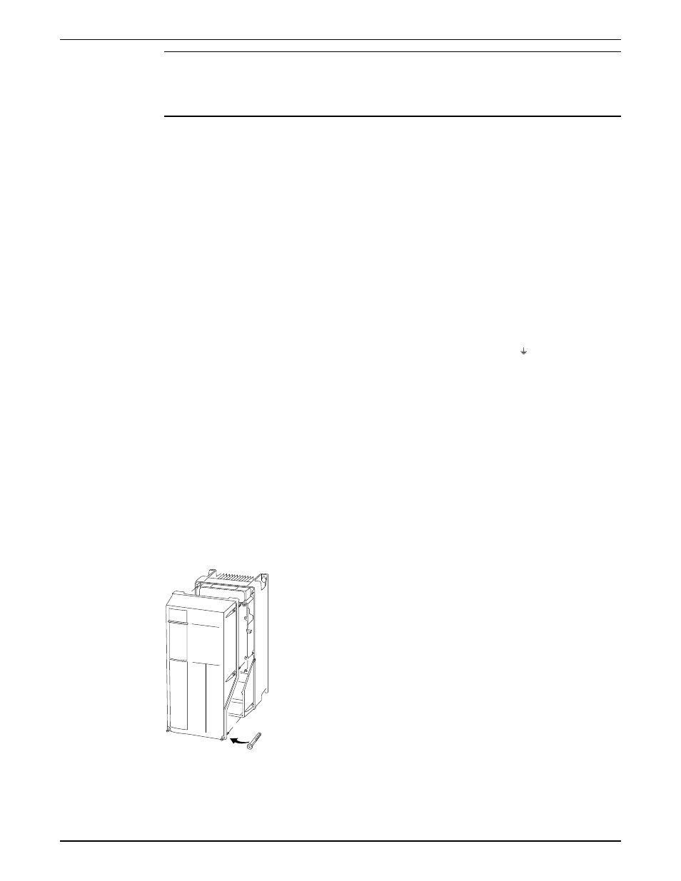
Control wiring access
• Remove front cover of unit to access internally mounted control terminals.
130BT334.10
Figure 2: Control terminals access
Electrical Installation
12
Integrated Technologic
®
with Sensorless Control INSTRUCTION MANUAL