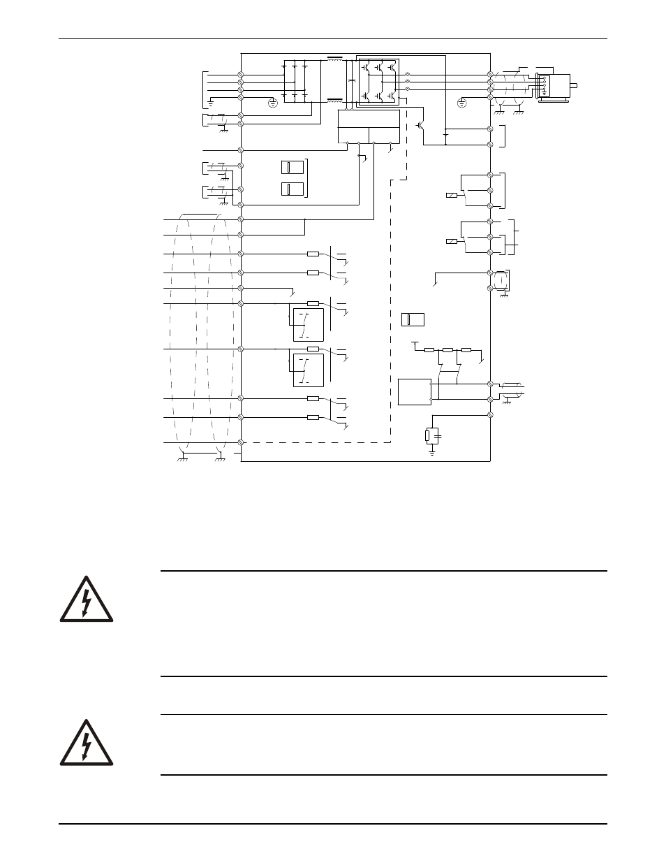
Line input (mains) connection, Figure 1: basic wiring schematic drawing, Electrical installation integrated technologic – Bell & Gossett P2001489 Integrated Technologic with Sensorless Control User Manual
Page 13: With sensorless control instruction manual 11
*
91 (L1)
92 (L2)
93 (L3)
PE
88 (-)
89 (+)
50 (+10 V OUT)
53 (A IN)
54 (A IN)
55 (COM A IN)
0/4-20 mA
12 (+24V OUT)
13 (+24V OUT)
18 (D IN)
20 (COM D IN)
15mA
200mA
(U) 96
(V) 97
(W) 98
(PE) 99
(COM A OUT) 39
(A OUT) 42
0/4-20 mA
03
0-10Vdc
+10Vdc
0-10Vdc
0/4-20 mA
240Vac, 2A
24Vdc
02
01
05
04
06
240Vac, 2A
24V (NPN)
0V (PNP)
0V (PNP)
24V (NPN)
19 (D IN)
24V (NPN)
0V (PNP)
27
24V
0V
(D IN/OUT)
0V (PNP)
24V (NPN)
(D IN/OUT)
0V
24V
29
24V (NPN)
0V (PNP)
0V (PNP)
24V (NPN)
33 (D IN)
32 (D IN)
1
2
ON
A53/S201
ON
2
1
A54/S202
ON=0-20mA
OFF=0-10V
95
400Vac, 2A
P 5-00
(R+) 82
(R-) 81
37 (D IN)
+
-
+
-
130BA544.12
(P RS-485) 68
(N RS-485) 69
(COM RS-485) 61
0V
5V
S801
RS-485
RS-485
2
1
ON
BUS TER./S801
3 Phase
power
input
DC bus
Switch Mode
Power Supply
Motor
Analog Output
Interface
relay1
relay2
ON=Terminated
OFF=Open
Brake
resistor
(NPN) = Sink
(PNP) = Source
Figure 1: Basic wiring schematic drawing
Fuses
For models with an optional fused disconnect installed, input fuses have been factory
installed in the enclosure. For models without a fused disconnect option, appropriate fuse
protection must be provided by the installer. Refer to the Technologic Pump Controller
IOM for a list of appropriate fuses for each model.
Electrical Hazard:
• Replacement fuses must be of the same continuous rating, fuse type and have the
same maximum interrupting rating as the fuse being replaced.
• Before replacing a blown fuse or resetting a circuit breaker, the source of the fault
causing the fuse to blow must be found and remedied.
• Before connecting the input power wiring or fusing, ensure all input disconnects or
breakers are set and locked to the off position.
Line input (mains) connection
Electrical Hazard:
For operator’s safety, it is important to ground drive properly. Failure to ground drive
properly could result in death or serious injury.
Electrical Installation
Integrated Technologic
®
with Sensorless Control INSTRUCTION MANUAL
11