Appendix c, Interference suppression measures – Xylem IM043 AQUAVAR Variable Speed Pump Control User Manual
Page 78
Interference Suppression Measures
Introduction
Electrical/electronic devices are capable of influencing or disturbing each other through connecting
cables or other metallic connections. Interference suppression measures (electromagnetic
compatibility) consists of two elements: interference resistance and interference emission.
Correct installation of the inverter in conjunction with any possible local interference suppression
measures has a crucial effect on minimizing or suppressing mutual interference.
guidelines for interference Suppression
The following guidelines assume a power source that is not contaminated by high frequency
interference. Other measures may be necessary to reduce or suppress interference if the power
source is contaminated, and no general recommendations can be given for such cases. Please
consult G&L Applications Engineering Department if the following recommended
interference suppression measures do not produce the desired result.
Guidelines are as follows:
• When dealing with RFI (radio frequency interference), the surface area of the conductors is a
more critical consideration than its cross sectional area. Since high frequency interference does
not flow through the entire cross section of the conductor, but tends to stay toward its outer
surface (skin effect), braided copper tapes of equal cross section should be used.
• A central grounding point should be used for interference suppression. Route the ground cables
radially from this point, avoiding loops which may lead to interference.
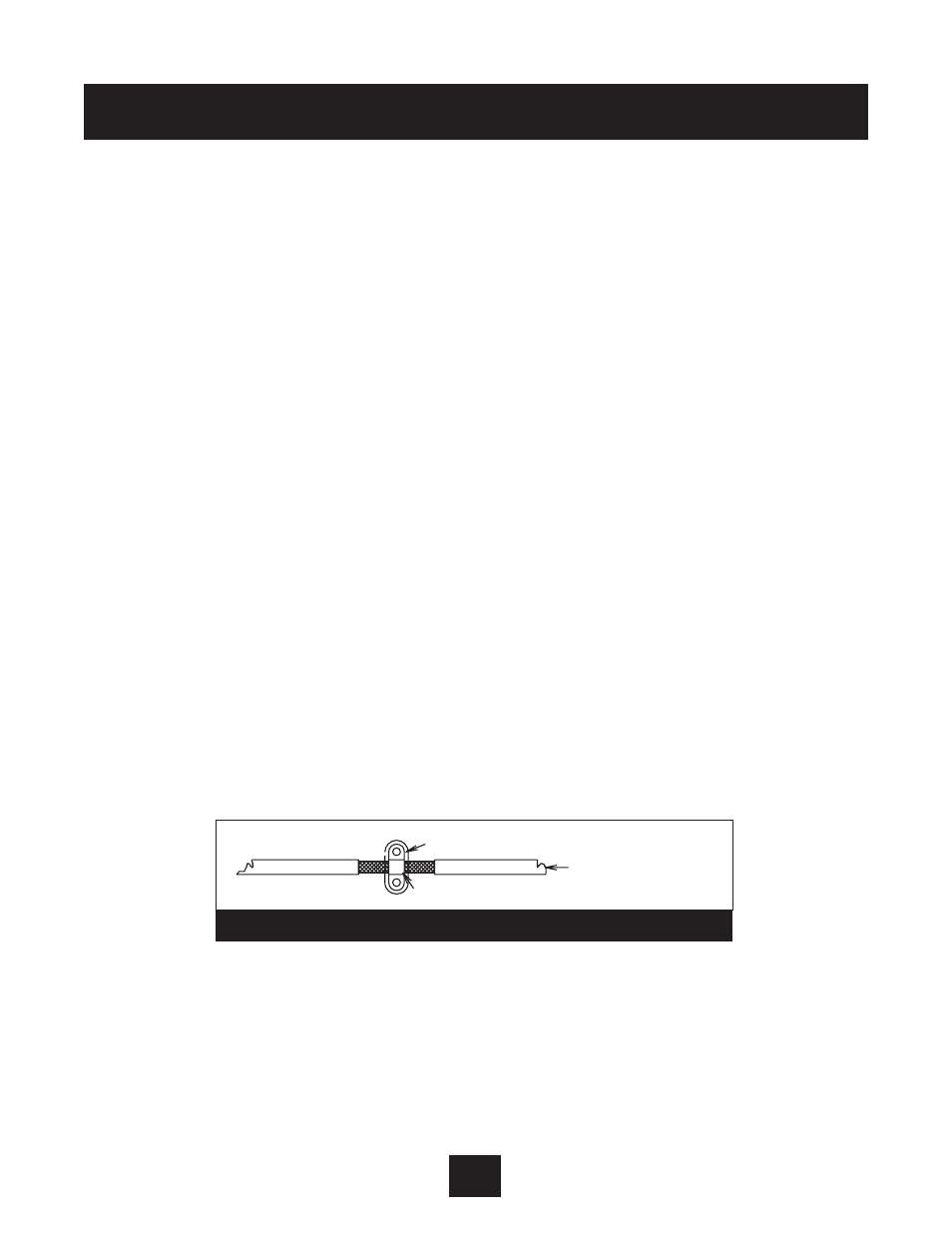
• The inverter and all components used for interference suppression, particularly the shield of the
motor cable, should be connected over as large a surface area as possible when passing over
metallic surfaces. Remove the paint from contact surfaces to ensure a good electrical
connection. See Diagram 25 for recommended connection technique.
Appendix C
77
Paint/varnish removed
Large contact area with shield
Shielded motor cable
Diagram 25