Aquavar, Installation procedures, Electrical connections continued – Xylem IM043 AQUAVAR Variable Speed Pump Control User Manual
Page 18: U, v, w
17
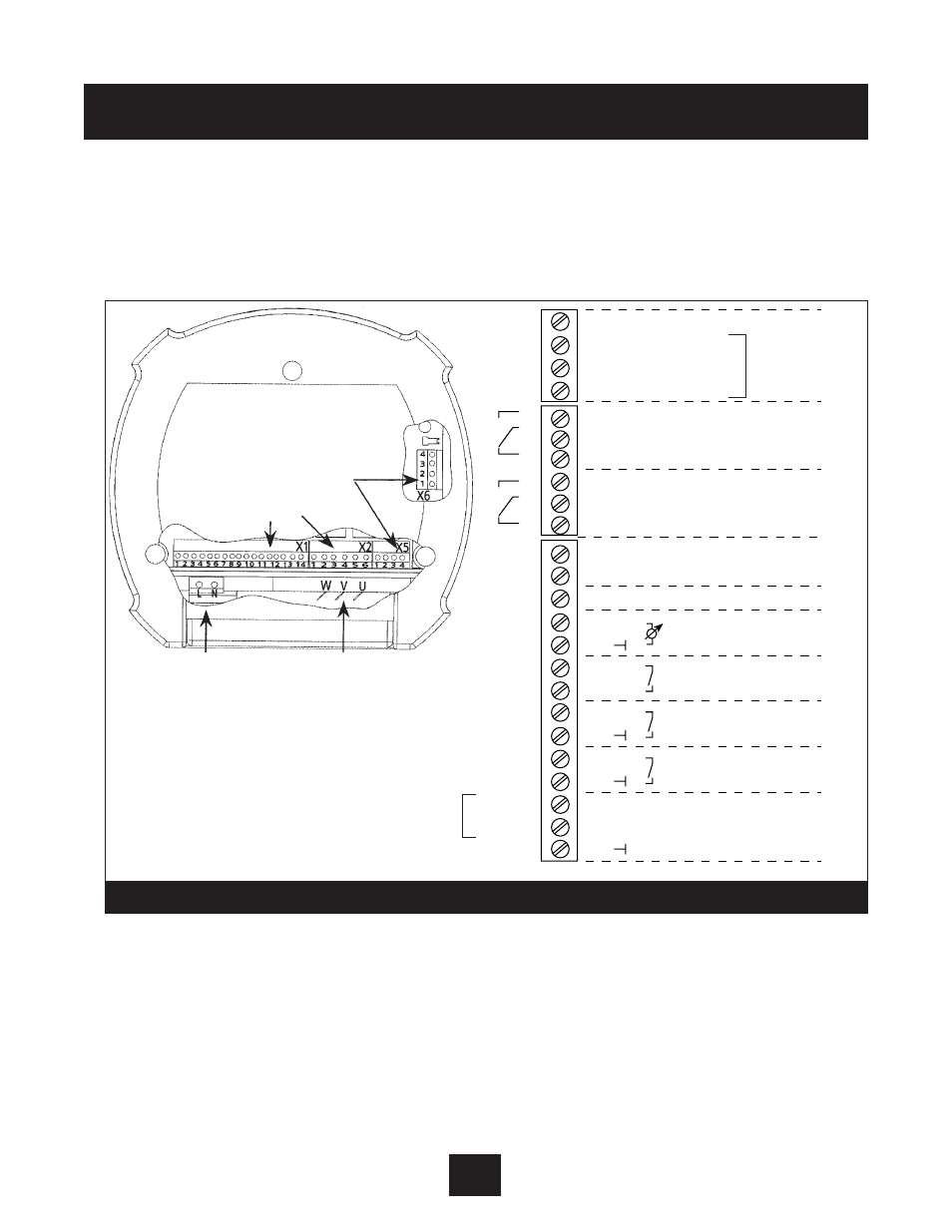
electrical Connections continued
10. Now select one of the ports in the AQUAVAR controller to route the trans-
ducer cable. Cut to length and connect to locations X1 #2 and #3 as shown in Diagram 8.
The brown wire is connected to X1 #3 and the white wire to X1 #2. Tighten strain relief.
11. Input Power Cable Installation
The main power cable is connected to the terminal block labeled L1, L2 (N) for the 230 volt
1phase input power units, and labeled L3, L2, and L1 for the 460 volt 3 phase input power
units; refer to Diagram 5.
12. Select one of the ports in the AQUAVAR controller to route the input power cable.
Installation Procedures
BROWN – 3
WHITE – 2
4
3
2
1
6
5
4
3
2
1
14
13
12
11
10
9
8
7
6
5
4
3
2
1
+ 5V
GND
SIO +
SIO -
15 V
IN
(4-20 mA)
RS-485
pump running signal
fault signal
Current Signal Input (4-20 mA)
Analog signal output (0-10V)
Motor thermo or PTC
low Water or jumper
external on or jumper
U
b
(max 100 mA)
actual value signal
shielding
X1
X2
Multi-
pump
Transducer
connection
Jump
Jump
X5
NO
CC
NC
NO
CC
NC
Digital Input
Voltage Signal Input (0-10Vor 2-10V)
AUBURN, NeW yORK 13021
•
PRESSURE?
•
AUTOSTART?
•
SAVE
•
START
•
STOP
or
(on) or
(off)
+
POWER
RUN
FAULT
I
D
S
S
�
S
�
�
�
S
�
�
�
�
�
�
AQUAVAR
TM
X2
6
5
4
3
2
1
12
11
10
9
8
7
6
5
4
3
2
1
X1
U
V W
L1
L2
SCh 60.05
MOTOR
MAIN POWER
13
14
X5
4
3
2
1
X4
4 3 2 1
PE
PE
RS485
AQUAVAR
®
RS485 Interface
Control Terminals
Power Supply
Motor Connection
1x230 VAC
3 Phase Out
L=L
1
, N=L
2
U, V, W
Diagram 8