Aquavar, Installation procedures, Electrical connections continued – Xylem IM043 AQUAVAR Variable Speed Pump Control User Manual
Page 16: U, v, w
15
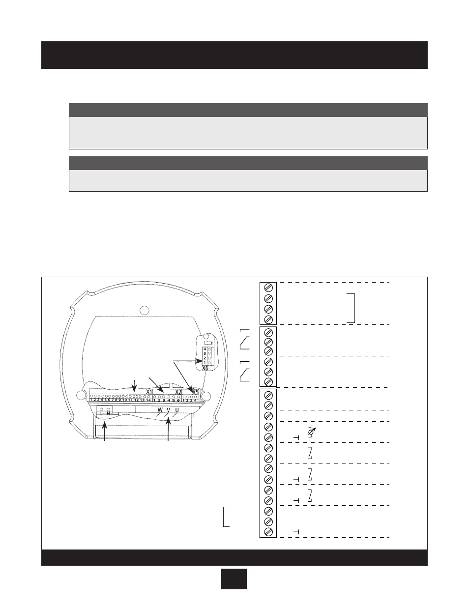
electrical Connections continued
4. Thermal Sensor Wire Connections
Locate the terminal block labeled X1 inside the AQUAVAR controller.
• Connect wires in terminal locations X1 #9 and #8 and route through the same threaded
port as the previous wires.
Installation Procedures
At this time, reference terminal block X1 locations, X1 #7 and #6, and X1 #5 and #4. If these connections are
not being used for a low water switch or an external switch, they must be jumped as shown on Diagram 6.
Note
Use two core shielded cables for the thermal sensor and approved UL shielded wire power cable for the motor.
Note
BROWN – 3
WHITE – 2
4
3
2
1
6
5
4
3
2
1
14
13
12
11
10
9
8
7
6
5
4
3
2
1
+ 5V
GND
SIO +
SIO -
15 V
IN
(4-20 mA)
RS-485
pump running signal
fault signal
Current Signal Input (4-20 mA)
Analog signal output (0-10V)
Motor thermo or PTC
low Water or jumper
external on or jumper
U
b
(max 100 mA)
actual value signal
shielding
X1
X2
Multi-
pump
Transducer
connection
Jump
Jump
X5
NO
CC
NC
NO
CC
NC
Digital Input
Voltage Signal Input (0-10Vor 2-10V)
AUBURN, NeW yORK 13021
•
PRESSURE?
•
AUTOSTART?
•
SAVE
•
START
•
STOP
or
(on) or
(off)
+
POWER
RUN
FAULT
I
D
S
S
�
S
�
�
�
S
�
�
�
�
�
�
AQUAVAR
TM
X2
6
5
4
3
2
1
12
11
10
9
8
7
6
5
4
3
2
1
X1
U
V W
L1
L2
SCh 60.05
MOTOR
MAIN POWER
13
14
X5
4
3
2
1
X4
4 3 2 1
PE
PE
RS485
AQUAVAR
®
RS485 Interface
Control Terminals
Power Supply
Motor Connection
1x230 VAC
3 Phase Out
L=L
1
, N=L
2
U, V, W
Diagram 6