Technical data, Motor connections, Cooling – r7/r8 – Xylem IM250R03 Aquavar CPC-FD User Manual
Page 32: Cable terminals
32
Motor Connections
Motor Connection Specifications – R7/R8
Motor Connection Specifications
Maximum Motor
Frame
Maximum Motor Cable Length*
Cable Length
Size f
sw
= 1 or 4 kHz
f
sw
= 8 kHz or 12 kHz
R7…R8
300 m
980 ft
Does not apply
WARNING! Using a motor cable longer than specified in the chart above may cause permanent
damage to the drive.
Cooling – R7/R8
Cooling Specifications
Method
Internal fan, flow direction from bottom to top.
• R7/R8: Free space in front of enclosure: 152 mm (6 in).
Requirement
• R7/R8: Free space above enclosure: None required for cooling.
• R7/R8: Free space at sides of enclosure: None required for cooling.
• R7/R8: Also see “Additional Free Space Recommendations” on page 33.
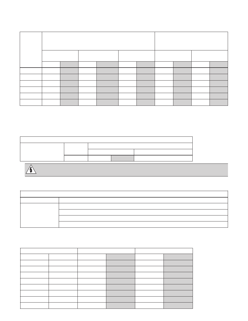
Air Flow, 380…480 Volt Drives – R7/R8
The following table lists heat loss and air flow data for 380…480 Volt drives.
Drive
Heat Loss
Air Flow
CPC-xx-
Frame Size
W
BTU/Hr
m
3
/h ft
3
/min
-245A-4
R7
3850
13000
300
540
-316A-4
R8
5300
18000
700
1220
-368A-4
R8
6850
23000
700
1220
-414A-4
R8
7000
24000
700
1220
-486A-4
R8
7600
26000
700
1220
-526A-4
R8
7800
27000
700
1220
-602A-4
R8
8100
28000
700
1220
-645A-4
R8
9100
31000
700
1220
TECHNICAL DATA
Frame
Size
U1, V1, W1
U2, V2, W2
BRK±, UDC± Terminals
Earthing PE Terminal
Minimum
Wire Size
Maximum
Wire Size
Tightening
Torque
Maximum
Wire Size
Tightening
Torque
mm
2
AWG
mm
2
AWG
N
•
m
lb
•
ft
mm
2
AWG
N
•
m
lb
•
ft
R1
1
0.75
18
10
8
1.4
1
10
8
1.4
1
R2
1
0.75
18
10
8
1.4
1
10
8
1.4
1
R3
1
2.5
14
25
3
2.5
1.8
16
6
1.8
1.3
R4
1
6
10
50
1/0
5.6
4
25
3
2
1.5
R5
1
6
10
70
2/0
15
11
70
2/0
15
11
R6
95
3/0
240
350 MCM
40
30
95
3/0
8
6
1 Aluminum cable cannot be used with frame sizes R1…R6 because of its lower capacity.
Note: See the recommended cable sizes for different load currents in section Cable Sizing/Ratings.
Cable Terminals
(Frames R1-R6)