Zxld1362, Application information (cont.) – Diodes ZXLD1362 User Manual
Page 19
ZXLD1362
ZXLD1362
Document number: DS33472 Rev. 5 - 2
19 of 24
May 2012
© Diodes Incorporated
A Product Line of
Diodes Incorporated
Application Information (cont.)
Inductor Selection
Recommended inductor values for the ZXLD1362 are in the
range 68
μH to 220μH.
Higher values of inductance are recommended at higher
supply voltages in order to minimize errors due to switching
delays, which result in increased ripple and lower efficiency.
Higher values of inductance also result in a smaller change in
output current over the supply voltage range. (see graphs
pages 10 - 17). The inductor should be mounted as close to
the device as possible with low resistance connections to the
LX and V
IN
pins.
The chosen coil should have a saturation current higher than
the peak output current and a continuous current rating above
the required mean output current.
Suitable coils for use with the ZXLD1362 may be selected from
the MSS range manufactured by Coilcraft, or the NPIS range
manufactured by NIC components. The following websites may
be useful in finding suitable components.
The inductor value should be chosen to maintain operating
duty cycle and switch 'on'/'off' times within the specified limits
over the supply voltage and load current range.
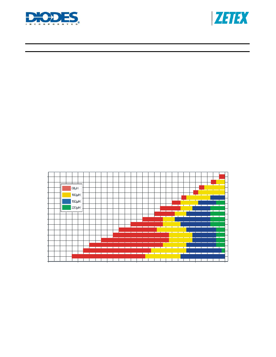
The graph Figure 3 below can be used to select a
recommended inductor based on maintaining the ZXLD1362
case temperature below 60°C. For detailed performance
characteristics for the inductor values 68, 100, 150 and 220
μH
see graphs on pages 10-17.
Figure 3. ZXLD1362 Minimum Recommended Inductor
Aluminium board, 2%Accuracy, <60°C CaseTemperature
0
1
2
3
4
5
6
7
8
9
10
11
12
13
14
15
16
0
10
20
30
40
50
60
Supply Voltage (V)
N
u
m
b
er
of
L
E
D
s
ZXLD1362 Minimum Recommended Inductor