Zxld1362, Application information (cont.) – Diodes ZXLD1362 User Manual
Page 18
ZXLD1362
ZXLD1362
Document number: DS33472 Rev. 5 - 2
18 of 24
May 2012
© Diodes Incorporated
A Product Line of
Diodes Incorporated
Application Information (cont.)
Shutdown Mode
Taking the ADJ pin to a voltage below 0.2V for more than
approximately 100µs will turn off the output and supply current
to a low standby level of 20µA nominal.
Note that the ADJ pin is not a logic input. Taking the ADJ pin to
a voltage above V
REF
will increase output current above the
100% nominal average value. (See page 18 graphs for details).
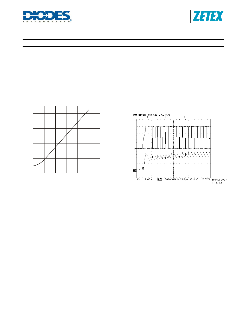
Soft-Start
An external capacitor from the ADJ pin to ground will provide a
soft-start delay, by increasing the time taken for the voltage on
this pin to rise to the turn-on threshold and by slowing down the
rate of rise of the control voltage at the input of the comparator.
Adding capacitance increases this delay by approximately
200µs/nF. The graph to the left shows the variation of soft-start
time for different values of capacitor.
40
60
0
20
80
100
120
CAPACITANCE (nF)
Soft Start Time vs. Capacitance from
ADJ Pin to Ground
16
14
12
10
4
2
0
-2
8
6
S
O
F
T
S
T
A
R
T
T
IME
(ms
)
Actual Operating Waveforms [V
IN
= 24V, R
S
= 0.1
Ω,
L = 68µH, 22nF on ADJ]
Soft-start operation. Output current (Ch2) and LX voltage (Ch1)
V
IN
Capacitor Selection
A low ESR capacitor should be used for input decoupling, as
the ESR of this capacitor appears in series with the supply
source impedance and lowers overall efficiency. This capacitor
has to supply the relatively high peak current to the coil and
smooth the current ripple on the input supply.
To avoid transients into the IC, the size of the input capacitor
will depend on the V
IN
voltage:
V
IN
= 6 to 40V C
IN
= 2.2
μF
V
IN
= 40 to 50V C
IN
= 4.7
μF
V
IN
= 50 to 60V C
IN
= 10
μF
When the input voltage is close to the output voltage the input
current increases which puts more demand on the input
capacitor. The minimum value of 2.2
μF may need to be
increased to 4.7
μF; higher values will improve performance at
lower input voltages, especially when the source impedance is
high. The input capacitor should be placed as close as possible
to the IC.
For maximum stability over temperature and voltage,
capacitors with X7R, X5R, or better dielectric is recommended.
Capacitors with Y5V dielectric are not suitable for decoupling in
this application and should NOT be used.
If higher voltages are used and the C
IN
is 10
μF. This can be an
electrolytic capacitor provide a suitable 1µF ceramic capacitor
is also used and positioned as close the V
IN
of the IC as
possible.
A suitable capacitor would be NACEW100M1006.3x8TR13F.
The following web sites are useful when finding alternatives: