2 controls and indicators, 1 co-mr controls and indicator – Armasight NSCCOMR00133DB1 CO-MR GEN 3 Bravo Day/night vision Clip-On system User Manual
Page 25
25
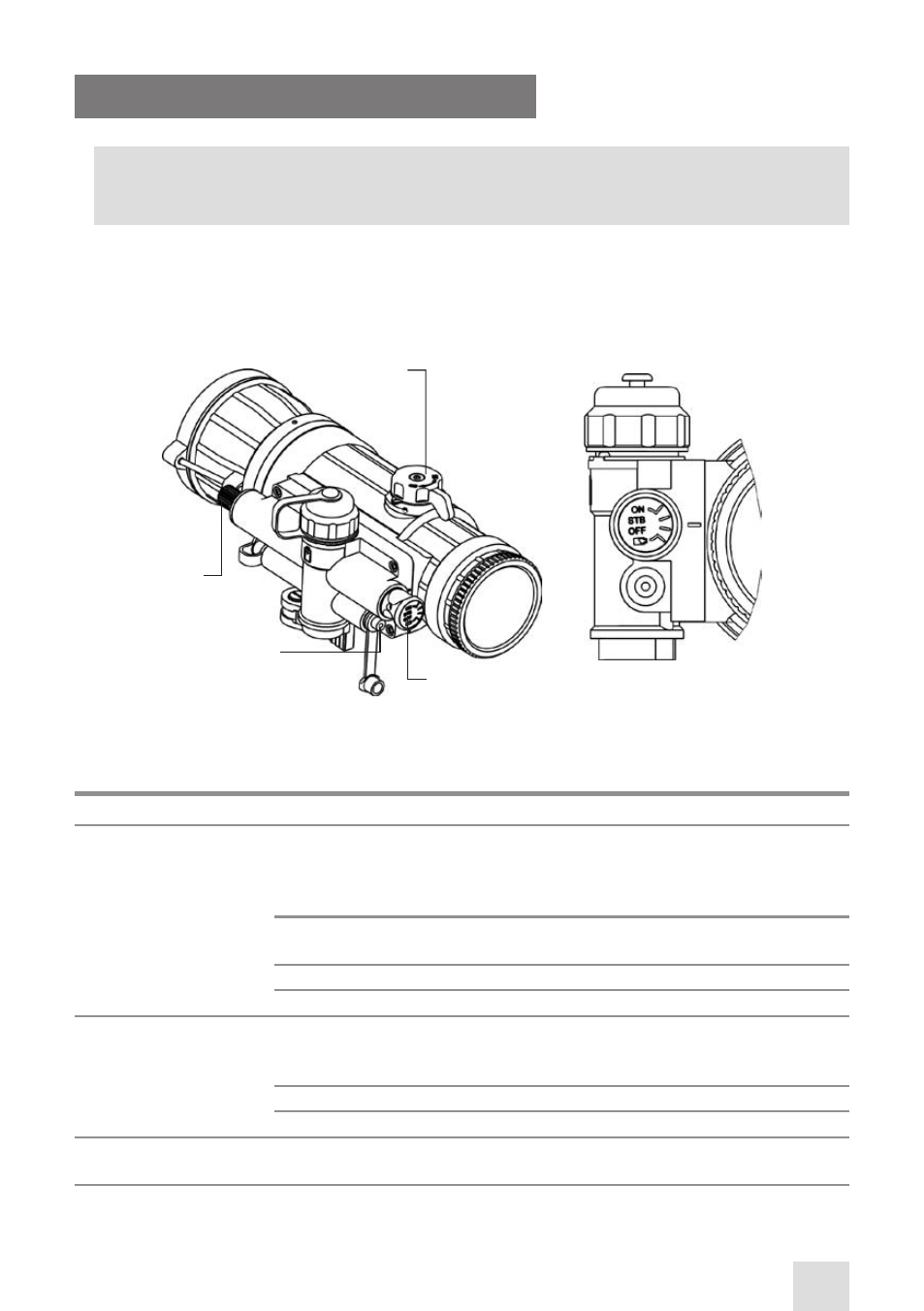
3.2 CONTROLS AND INDICATORS
CAUTION:
DO NOT force the equipment controls past their stopping points.
3.2.1 CO-MR CONTROLS AND INDICATOR
The CO-MR controls and indicator are shown in Figure 3-14 and defined in Table 3-1. The ITEM NO. col-
umn indicates the number used to identify items in Figure 3-14.
TABLE 3-1. CO-MR CONTROLS AND INDICATOR
ITEM NO. CONTROL/INDICATOR
FUNCTION
1
Turn-Pull Switch Activates the CO-MR, when turned to ON position.
NOTE:
Both ON and “BATTERY” end positions of the switch can only be entered
if the spindle is pulled before turning.
Actuates the battery check mode, when turned to “BATTERY” position (see
note above).
Actuates standby mode, when turned to STB.
Deactivates the CO-MR, when turned to OFF.
2
Bi-color LED
Indicator
PERMANENT GREEN GLOW indicates excessive light conditions. After 10
seconds the image intensifier tube will be cut off. The CO-MR turns back
again when moved away from the excessive light.
PERMANENT RED GLOW indicates usable condition of the battery.
FLASHING RED LIGHT indicates a low battery.
3
Gain Control
Knob*
Adjusts the brightness of the image.
FIGURE 3-14. CO-MR CONTROLS AND INDICATOR
4
3
1
2
- NSCCOMR00133DA1 CO-MR GEN 3 Alpha Day/night vision Clip-On system NSCCOMR001P3DA1 CO-MR GEN 3P Day/night vision Clip-On system NSCCOMR001GMDA1 CO-MR GEN 3 Ghost MG Day/night vision Clip-On system NSCCOMR0012MDS1 CO-MR GEN 2+ SD MG Day/night vision Clip-On system NSCCOMR0012MDI1 CO-MR GEN 2+ ID MG Night Vision Medium Range Clip-On System NSCCOMR00123DH1 CO-MR GEN 2+ HD Day/night vision Clip-On system NSCCOMR001QMDI1 CO-MR GEN 2+ QS MG Day/night vision Clip-On system