4 clamping device adjustment – Armasight NSCCOMR00133DB1 CO-MR GEN 3 Bravo Day/night vision Clip-On system User Manual
Page 20
20
5. Affix the CO-MR to the rail by locking the cam lever (B, see Figure 3-4).
6. Verify that the clamping device is firmly holding the CO-MR. If necessary, adjust the clamping device
as detailed in Part 3.1.4 (Clamping Device Adjustment).
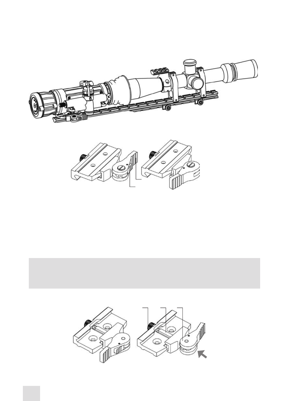
Figure 3-3 shows the CO-MR and a day scope installed with the optional Extended Rail Adapter on a
weapon, using a short-mounting Picatinny/ Weaver rail.
FIGURE 3-3. THE CO-MR ON A PICATINNY RAIL IN FRONT OF A DAY SCOPE
3.1.4 CLAMPING DEVICE ADjUSTMENT
Adjust the mount clamping device as follows (refer to Figure 3-5):
1. Unlock the clamping device and remove the CO-MR from the weapon.
2. To tighten/loosen the clamping device, push the cam (C) towards the arrow (which will cause the nut
(A) to slide out of its hollow) and turn the nut (A) CW/CCW respectively, in one-two increments (see
note below). Much like when the cam (C) is released, backward-moving springs will cause the nut (A)
to slide back into its hollow.
NOTE
:
The eight-sided nut of the clamping device will only fit into its hollow if turned in one of the
discrete positions using increment equal to 360°/8.
4. Verify that the adjusted lever-cam lock holds the mounting rail firmly.
A
B
C
UNLOCK
POSITION
LOCKEd
POSITION
FIGURE 3-5. MOUNT. UNDERSIDE VIEW
FIGURE 3-4. MOUNT. TOP VIEW
B
A
LOCKEd
POSITION
UNLOCK
POSITION
- NSCCOMR00133DA1 CO-MR GEN 3 Alpha Day/night vision Clip-On system NSCCOMR001P3DA1 CO-MR GEN 3P Day/night vision Clip-On system NSCCOMR001GMDA1 CO-MR GEN 3 Ghost MG Day/night vision Clip-On system NSCCOMR0012MDS1 CO-MR GEN 2+ SD MG Day/night vision Clip-On system NSCCOMR0012MDI1 CO-MR GEN 2+ ID MG Night Vision Medium Range Clip-On System NSCCOMR00123DH1 CO-MR GEN 2+ HD Day/night vision Clip-On system NSCCOMR001QMDI1 CO-MR GEN 2+ QS MG Day/night vision Clip-On system