4 maintenance – Armasight NSCCOLR00139DA1 CO-LR GEN 3 Alpha MG Night Vision Long Range Clip-On System User Manual
Page 34
34
4.4 MAINTENANCE
4.4.1 GENERAL
The section regarding CO-LR operator maintenance consists of operational tests, inspections for unit
serviceability, cleaning and mounting procedures, troubleshooting, and replacement instructions for
a limited number of parts. Maintenance instructions covered elsewhere in this manual (PMCS, trouble-
shooting, etc.) are not repeated in this section.
CAUTION:
The CO-LR is a precision electron-optical instrument, and must be handled carefully at all times
to prevent damage to the device’s body or mechanisms.
4.4.2 CLEANING PROCEDURES
CAUTION:
Thoroughly dry each item before placing them into the storage case.
Clean the CO-LR as follows:
1. Gently brush off any dirt from the unit’s body using a clean, soft cloth.
2. Moisten the cloth with fresh water and gently wipe external surfaces (except for glass surfaces).
3. Dry any wet surfaces (except for glass surfaces) with another clean, soft, dry cloth.
4. Using a lens brush, carefully remove all loose dirt from the glass surfaces.
5. Slightly dampen a cotton swab with ethanol. Gently and slowly wipe the lenses (including the pho-
toreceiver and the pivotal focusing lens). Without touching the lens holders, clean the glass surfaces
in circular movements, beginning in the center and moving out towards the edge. Change the cot-
ton swab after each circular stroke. Repeat until the glass surfaces are clean.
6. Clean the battery contact surfaces and contact springs with a pencil eraser and/ or alcohol-damp-
ened cotton swabs.
Clean optional devices with a soft brush (cloth), soap, and water as required.
4.4.3 BATTERY REMOVAL AND REPLACEMENT
Refer to Part 3.1.1 for the CO-LR and IR850 battery installation procedure.
Replace the remote control batteries as follows:
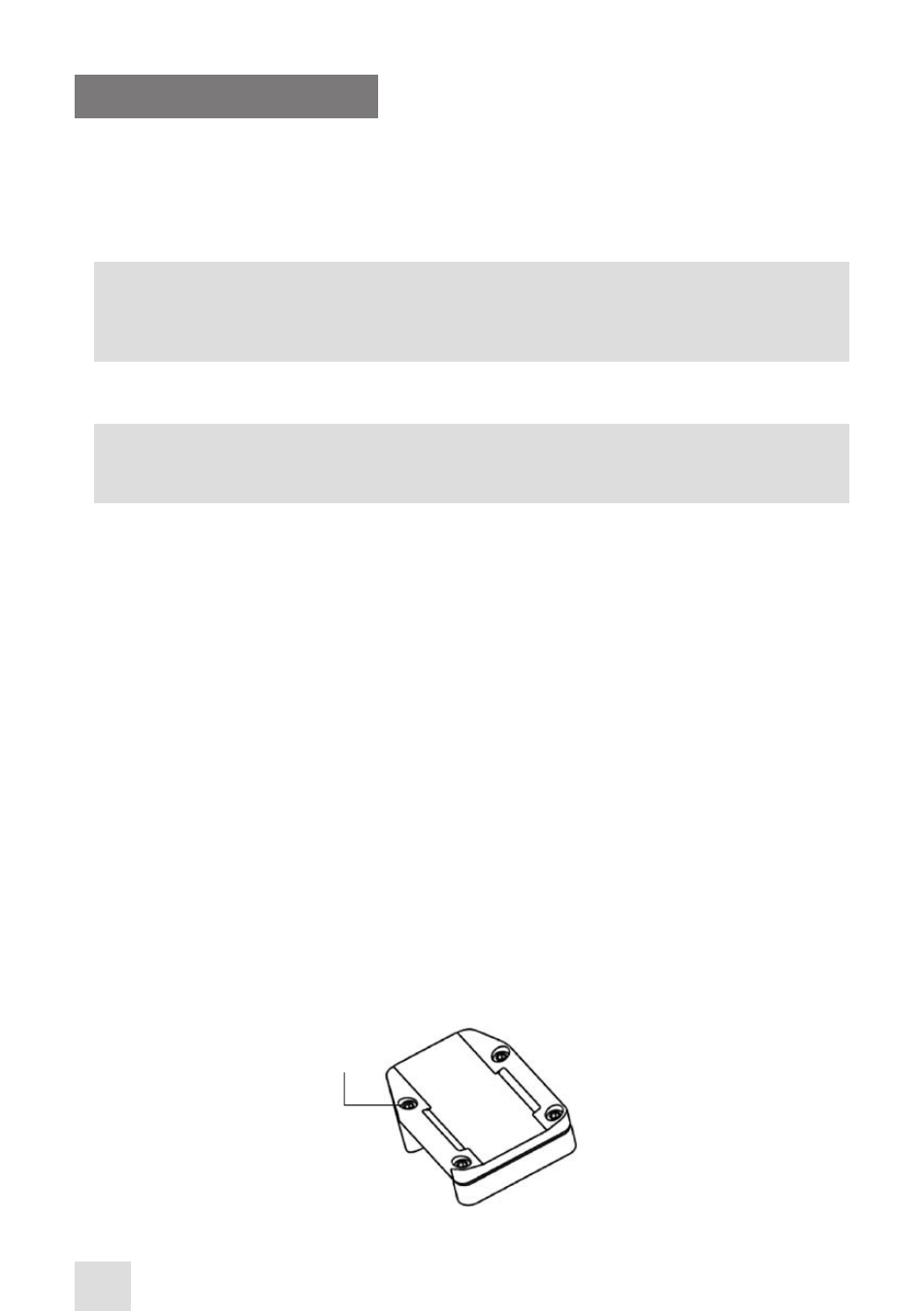
1. Using a screwdriver, unscrew the four screws (A, Figure 4-6) that affix the cover to the bottom of the
unit. Remove the cover.
2. Replace the batteries with two new ones (CR2016, 3V). Stack the batteries in its place under the leaf
contact spring with the minus contacts directed towards the electric board, as the minus sign etched
on the board indicates.
3. Replace the cover and retighten the screws (A).
FIGURE 3-11. ADVANCED WIRELESS REMOTE CONTROL. BATTERY INSTALLATION
A
- NSCCOLR001P9DA1 CO-LR GEN 3P MG Night Vision Long Range Clip-On System NSCCOLR001G9DA1 CO-LR GEN 3 Ghost MG Day/night vision Clip-On system NSCCOLR001F9DA1 CO-LR Flag MG Day/night vision Clip-On system SCCOLR00129DH1 CO-LR GEN 2+ HD MG Day/night vision Clip-On system NSCCOLR001Q9DI1 CO-LR GEN 2+ QS MG Day/night vision Clip-On system