Hardware setup, Asus sp98-n user’s manual 35 – Asus SP98-N User Manual
Page 35
ASUS SP98-N User’s Manual
35
3. HARDWARE SETUP
Connectors
3. H/W SETUP
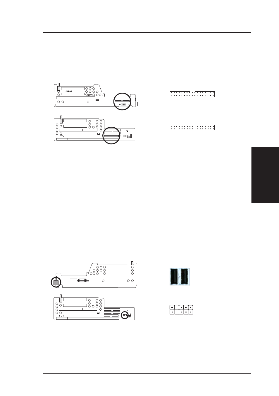
5) 3.5” Floppy Disk Drive Connector
This connector supports the provided floppy drive ribbon cable. After connect-
ing the single end to the riser card, connect the other end to a 3.5” floppy disk
drive. (Pin 5 is removed to prevent inserting in the wrong orientation when
using ribbon cables with pin 5 plugged).
Floppy Disk Drive Connector
Orient the red stripe on the
floppy ribbon cable to Pin 1
Pin 1
NLX-R (Front)
Yeong-Yang (Front)
®
NLX-R
YEONG-YANG
Pin 1
Yeong-Yang Risers
NLX-R Riser
6) Universal Serial Bus (USB) Ports / USB Module Connector
If you have the NLX-R or B9-N risers, two Universal Serial Bus (USB) ports
are available for connecting USB devices. If you have the Yeong-Yang riser, a 5-
pin block is available for connecting an external connector set. This connector
set can be mounted to an open slot on your computer’s chassis. USB Function
must be set to Enabled and USB IRQ to Auto in 4.4.3 PCI Configuration to
use USB features.
Universal Serial Bus (USB) Ports / USB Module Connector
NLX-R (Back)
Yeong-Yang (Front)
YEONG-YANG
1: USB +5 Volt
2: (no connection)
3: USB Port 0+
4: USB Port 0-
5: USB +5Volt
The USB ports show
through the front
panel
Port 1 Port 2
NLX-R Riser
1
5
Yeong-Yang Riser