GE Industrial Solutions QW010-015-020 Series User Manual
Page 5
Tyco Electronics Power Systems
5
Data Sheet
August 22, 2006
36 Vdc to 75 Vdc Input; 1.2 Vdc to 5.0 Vdc Output; 10 A to 20 A
QW010/015/020 Series Power Modules: dc-dc Converters;
Feature Specifications
Unless otherwise indicated, specifications apply over all operating input voltage, resistive load, and temperature conditions. See
Feature Descriptions for additional information
.
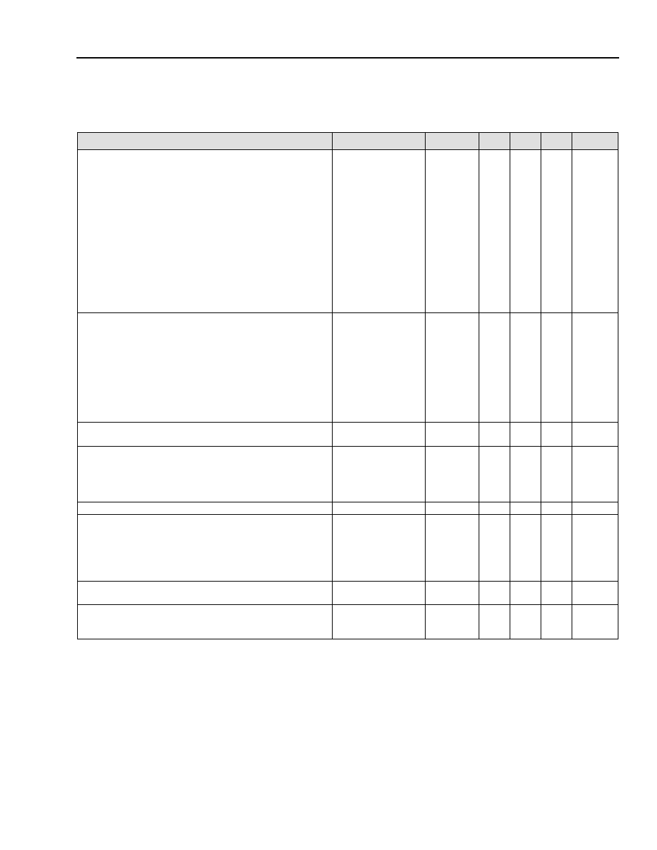
Parameter
Device
Symbol
Min
Typ
Max
Unit
Remote On/Off Signal Interface
(VI = VI,min to VI,max; open collector or compatible, signal
referenced to VI(–) terminal)
Negative Logic: Device Code Suffix “1”:
Logic Low—Module On / Logic High—Module Off
Positive Logic: If Device Code Suffix “1” Is Not Specified:
Logic Low—Module Off / Logic High—Module On
Module Specifications:
On/Off Current—Logic Low
On/Off Voltage—Logic Low
On/Off Voltage—Logic High (Ion/off = 0 mA)
Open Collector Switch Specifications:
Leakage Current During Logic High (Von/off = 15 V)
Output Low Voltage During Logic Low (Ion/off = 1 mA)
All
All
All
All
All
Ion/off
Von/off
Von/off
Ion/off
Von/off
—
–0.7
—
—
—
—
—
—
—
—
1.0
1.2
15
50
1.2
mA
V
V
µA
V
Turn-on Delay and Rise Times
(at 80% of IO, max; TA = 25 °C):
Case 1: On/Off Input Is Set for Logic High and then Input
Power Is Applied (delay from point at which VI = VI, min until
VO = 10% of VO, set).
Case 2: Input Power Is Applied for at Least One Second, and
Then the On/Off Input Is Set to Logic High (delay from point at
which Von/off = 0.9 V until VO = 10% of VO, set).
Output Voltage Rise Time (time for VO to rise from 10% of
VO, nom to 90% of VO, set)
All
All
All
Tdelay
Tdelay
Trise
—
—
—
17
3
13
—
—
—
ms
ms
ms
Output voltage overshoot
(IO = 80% of IO,max, VI = 48 Vdc TA = 25 °C)
All
—
—
5
%VO,set
Output Voltage Adjustment (See Feature Descriptions section):
Output Voltage Remote-sense Range
P,M,Y
G,F,A
—
—
0.25
10
V
%VO, set
Output Voltage Set-point Adjustment Range (trim)
All
90
—
110
%VO, set
Output Overvoltage Protection (clamp)
P
M
Y
G
F
A
VO, ovsd
VO, ovsd
VO, ovsd
VO, ovsd
VO, ovsd
VO, ovsd
2.0
2.3
2.3
2.7
3.6
5.5
—
—
—
—
—
—
2.4
2.7
2.7
3.7
4.5
7.2
V
V
V
V
V
V
Overtemperature Protection (VI = 75 V, IO = IO, max)
See Figure 44
All
TQ10 /
TQ560
—
120
—
°C
Input Undervoltage Lockout:
Turn-on Threshold
Turn-off Threshold
All
All
—
33
35
34
36
—
V
V