3 rpa parallel system, Rpa parallel system, Fig. 4.3-1 rpa system diagram – GE Industrial Solutions LP33 Series 80 & 100 User Manual User Manual
Page 16
Modifications reserved
Page 16/66
OPM_LPS_3UO_80K_M10_1US_V010.doc
User Manual LP33 Series 80 & 100 UL S1
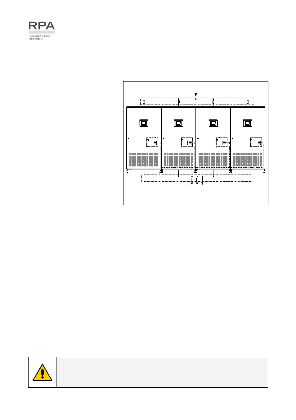
4.3 RPA PARALLEL SYSTEM
The RPA (Redundant Parallel Architecture) allows to extend the unit to a parallel system with 2, 3, or 4
units LP33 Series 80 & 100 connected on the same bus, which ensure the highest reliability rate and
increase the power availability.
Parallel system for power capacity
Two or more units can be paralleled in
order to achieve output power superior
to the maximum power delivered by a
single UPS unit.
The maximum total load shared
between the n parallel units can
achieve the 100% of the installed
nominal power system.
In the event of one unit fails, the load
will be suddenly transferred to the
mains by the bypass.
Parallel system for redundancy
The parallel system can be defined
redundant only in case the nominal
power rating of n-1 units of n parallel
units is sufficient to supply the required
load power.
LPS33U_080-100_RPA system_GE_01US
Digital Energy
g
UPS System
F1
F2
F3
F4
UTILITY INPUT
LP33 Series 80 & 100
1
2
3
4
LOAD
RPA
Board
RPA
Board
RPA
Board
RPA
Board
Digital Energy
g
UPS System
Digital Energy
g
UPS System
Digital Energy
g
UPS System
LP33 Series 80 & 100
LP33 Series 80 & 100
LP33 Series 80 & 100
Fig. 4.3-1 RPA system diagram
The load in a parallel redundant system, is equally shared by n units connected on the output bars.
Should one of the parallel units trip off-line, the remaining (n-1) units will share the load maintaining the
applications protected by inverter until the normal situation restores.
Load sharing between parallel units
The control bus exchanging the data between the microprocessors of the paralleled units provide for a
constant proportional load sharing in every load condition.
Management and synchronization of the parallel system
All the units are identical without master and slave relationship.
One unit is arbitrarily selected as the reference (the first unit connected on power bus) being this unit the
first synchronized with the mains voltage, and all the other units synchronize with the first one.
In case the reference unit fails or it is excluded from the parallel power bus any other unit will take over
the reference role.
The AC input power source of all the bypasses must be the same for all the units of the parallel system
excluding any phase shift between them.
Control bus of the parallel system
A high-speed serial bus, guarantees communication, synchronization and load sharing between the
UPS modules.
Each module controls it’s own function, while the Master (each unit can be Master) controls and
commands the status of the system.
NOTE !
The parallel system excludes more rectifiers connected on common battery.
No transformers, fuses or automatic circuit breakers should be inserted between
the unit’s output and the load common bus bars.