4 description, 1 block diagram and main elements description, Description – GE Industrial Solutions LP33 Series 80 & 100 User Manual User Manual
Page 12: Block diagram and main elements description
Modifications reserved
Page 12/66
OPM_LPS_3UO_80K_M10_1US_V010.doc
User Manual LP33 Series 80 & 100 UL S1
4 DESCRIPTION
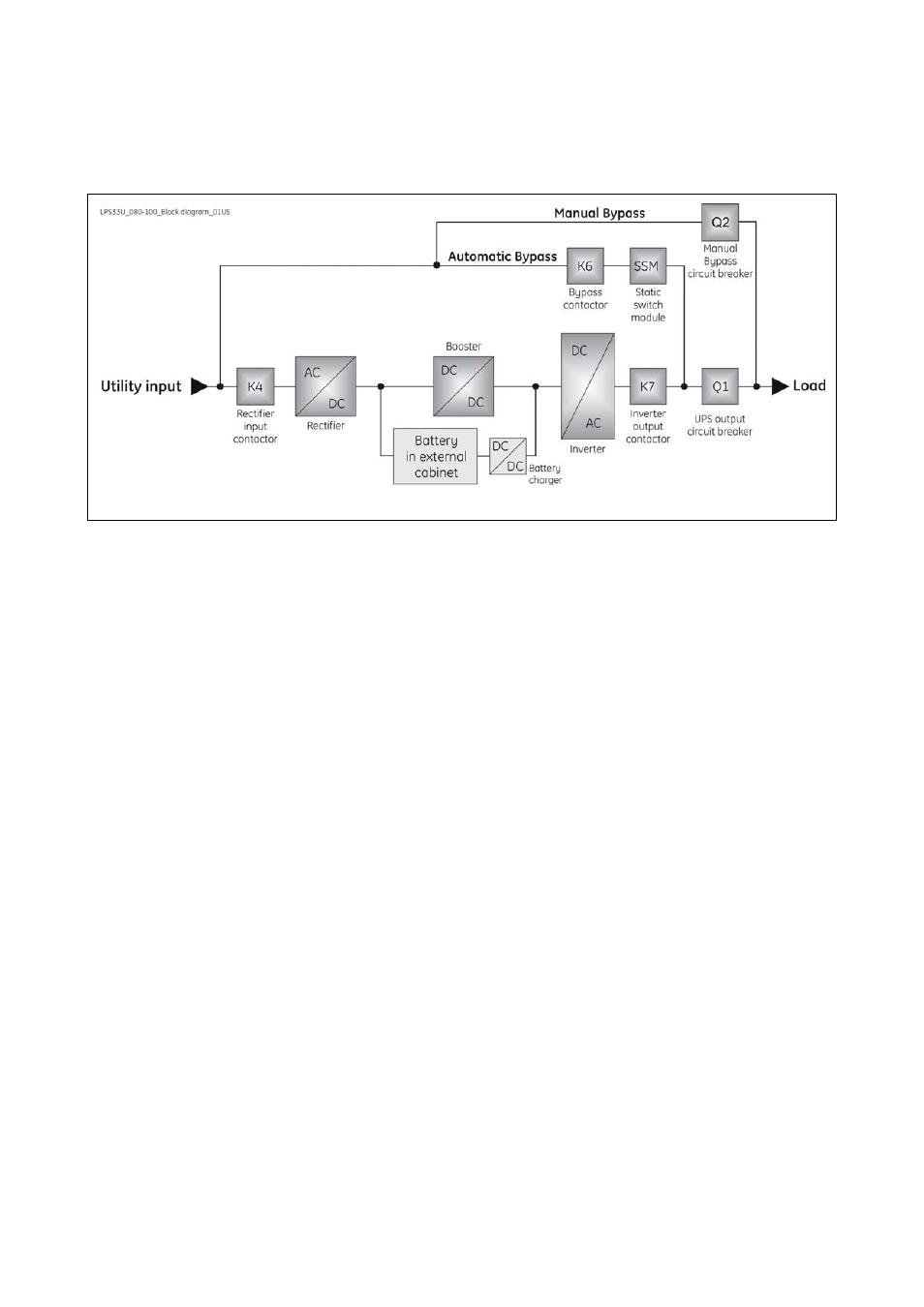
4.1 BLOCK DIAGRAM AND MAIN ELEMENTS DESCRIPTION
Fig. 4.1-1 UPS
block diagram
The Uninterruptible Power Supply System LP33 Series 80 & 100 can be divided into the following main
elements:
Electronics
The UPS is designed with a microprocessor–controlled supervision and diagnostic system.
Communication between user and UPS is achieved by the front panel consisting of an graphical LCD
screen, displaying the operation modes, the measurements and the events / alarms.
Rectifier
The rectifier converts the 3-phase mains voltage into a controlled and regulated DC-voltage, in order to
supply power to the booster, and to charge the battery through the battery-charger.
Inverter
The inverter converts the DC voltage into a three-phase AC-voltage with constant amplitude and
frequency, which is completely independent from the AC-input voltage.
Automatic Bypass
The automatic bypass consists of a static semiconductor-switch (SSR: Static Switch Relay), used to
provide an uninterrupted transfer of the load from inverter to mains when operating in VFI Mode.
If ECO Mode is enabled, the Static Switch Module (SSM) will transfer load from utility to inverter in case
the utility power anomaly.
Back-Feed Protection
All LP33 Series UPS’s are equipped with an automatic system for the protection against voltage back
feeding towards Utility, through the Bypass (Applied Standard IEC 62040-1).
This protection works automatically by opening contactor K6 (in series with the thyristors of the static
switch) and eventually K7, and acts in case of internal defects of the system, or due to incorrect
operation of the maintenance bypass Q2.
Manual Bypass
The manual bypass consists of a pair of manual switches Q1 and Q2, which allow the isolation of the
UPS from the load, while still supplying the load with power directly from the mains.
Battery
The battery, normally charged by the battery-charger, supplies the DC energy to inverter in the event
of mains failure.