Data sheet, Thermal considerations (continued) – GE Industrial Solutions JRCK017A0S32R0 Orca Series User Manual
Page 11
GE
Data Sheet
JRCK017A0S32R0 Orca Series; DC-DC Converter Power Modules
36–62 Vdc Input; 32.0Vdc Output; 17.0Adc Output
October 11, 2013
©2012 General Electric Company. All rights reserved.
Page 11
Thermal Considerations (continued)
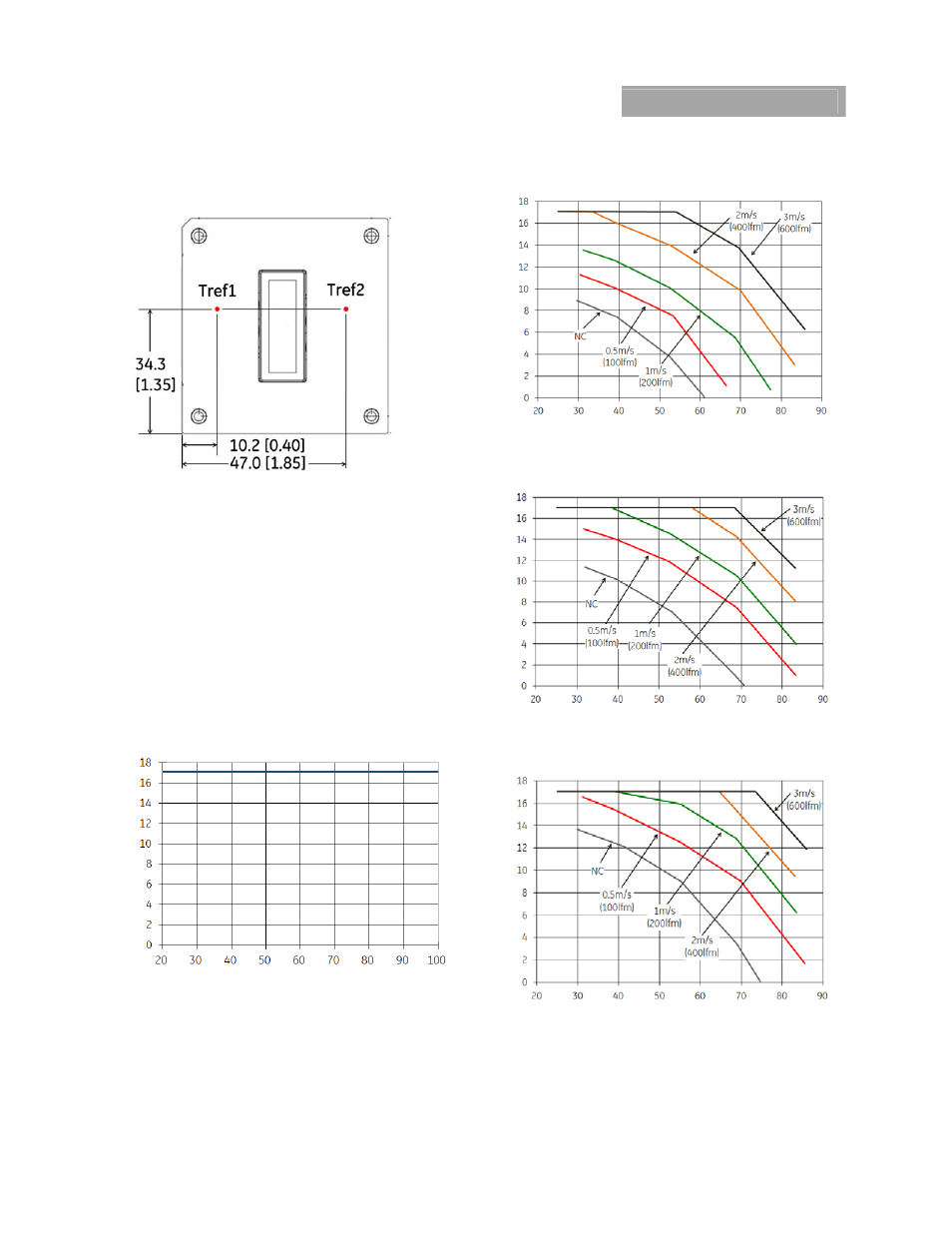
Figure 18.
Case (Tref
) Temperature Measurement Locations
(top view).
Thermal Derating
Thermal derating is presented for two different applications:
1) Figure 19, the JRCK017S32R0 module is thermally coupled
to a cold plate inside a sealed clamshell chassis, without any
internal air circulation; and 2) Figure 20, 21 and 22, the
JRCK017S32R0 module is mounted in a traditional open
chassis or cards with forced air flow. In application 1, the
module is cooled entirely by conduction of heat from the
module primarily through the top surface to a cold plate, with
some conduction through the module’s pins to the power
layers in the system board. For application 2, the module is
cooled by heat removal into a forced airflow that passes
through the interior of the module and over the top base plate
and/or attached heatsink.
Output
Curr
ent, I
O
(A)
Cold plate (inside surface) temperature (ºC)
Figure 19. Output Power Derating for JRCK017S32R0 in
Conduction cooling (cold plate) applications; T
a
<70ºC
adjacent to module; V
IN
= V
IN,NOM
O
utput Cur
rent, I
O
(A)
Ambient Temperature, T
A
(
o
C)
Figure 20. Derating Output Current vs. local Ambient
temperature and Airflow, No Heatsink, Vin=48V, airflow
from Vi(-) to Vi(+).
Output C
urrent,
I
O
(A
)
Ambient Temperature, T
A
(
o
C)
Figure 21. Derating Output Current vs. local Ambient
temperature and Airflow, 0.5” Heatsink, Vin=48V,
airflow from Vi(-) to Vi(+).
Output C
urrent,
I
O
(A
)
Ambient Temperature, T
A
(
o
C)
Figure 22. Derating Output Current vs. local Ambient
temperature and Airflow, 1.0” Heatsink, Vin=48V,
airflow from Vi(-) to Vi(+).