Locking the rotary handle assembly – GE Industrial Solutions Record Plus TDM, NEMA 1, 3R, 12: FC100 User Manual
Page 6
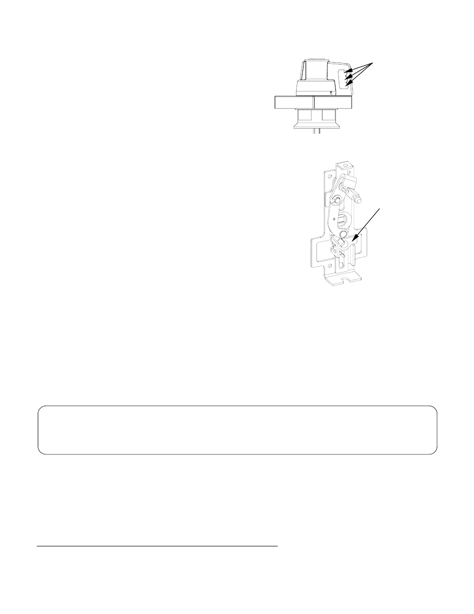
Locking the Rotary Handle
Assembly
Figure 15a. Locking rotary handle assembly.
One to three pad
Locks can be
introduced to lock
the rotary handle.
The rotary handle assembly is designed to
accommodate from one to three 0.2 in. (5 mm) to
0.315 in. (8 mm) padlocks to lock the breaker in
the
”OFF”
position, as shown in Figure 15a.
Push the slider down to
” Reset”
position of
breaker and insert the padlock shaft into the slot in
the padlock lever, to prevent closing the breaker
during maintenance, illustrated in
Figure 15b
.
Figure 15b. Locking the circuit breaker operating
mechanism.
Pad lock lever
These instructions do not cover all details or variations in equipment nor do they provide for every possible
contingency that may be met in connection with installation, operation, or maintenance. Should further
information be desired or should particular problems arise that are not covered sufficiently for the purchaser’s
purposes, the matter should be referred to the GE Company. The circuit breaker is a sealed unit that contains no
user-serviceable parts. Tampering with the seal will void the warranty.
g
GE Industrial Systems
________________________________________________________
General Electric Company
41 Woodford Ave., Plainville, CT 06062
www.geindustrial.com
DEH40517 R02 1003
© 2003 General Electric Company