Step 3 – install the rotary handle – GE Industrial Solutions Record Plus TDM, NEMA 1, 3R, 12: FC100 User Manual
Page 4
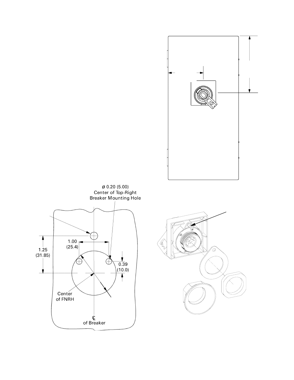
Step 3 – Install the Rotary Handle
1.
Drill holes on the enclosure door to
accommodate mounting the handle assembly, as
shown in Figure 9. The handle location on the
door is illustrated in Figure 10. Be sure that the
larger hole in Figure 9 is centered over the end
of the crank assembly or the extension shaft, as
appropriate.
3.15 min
(80.0)
3.15 min
(80.0)
2.
Place the rotary handle assembly [6] on the
door with the locating feature, shown in Figure
11, placed in the small hole drilled in step 1.
3.
Secure the handle assembly to the door as
follows, depending on which kit variant you are
using:
a. For kit FCNRN, use the plastic nut [5] to
secure the handle to the door.
b. For kit FCNRT, if the length L of the shaft
[9] is less than 9.8 inches (250 mm), use
the plastic nut [5] to secure the handle to
the door. If the shaft is longer than 9.8
inches (250 mm), use the funnel [10] to
secure the handle to the door.
4.
Close the enclosure door and verify that the end
of the crank assembly or the extension shaft, as
appropriate, locks into the center of the handle
Figure 10. FNRH handle location on the enclosure door.
Figure 9. Hole pattern for mounting the handle assembly on the
enclosure door.
Ø 0.236
(6.00)
on Door
Ø1.46
(37.00)
on Door
[5]
[10]
[6]
Locating
Feature
[11]
Figure 11. Installing the rotary handle assembly.