Feature descriptions, Austin superlynx, Continued) remote sense – GE Industrial Solutions Austin SuperLynx SMT User Manual
Page 14: Lineage power 14, The austin superlynx, Figure 32. remote sense circuit configuration
Data Sheet
September 3, 2013
Austin Superlynx
TM
SMT Non-isolated Power Modules:
3.0 – 5.5Vdc input; 0.75Vdc to 3.63Vdc Output; 16A output current
LINEAGE
POWER
14
Feature Descriptions
(continued)
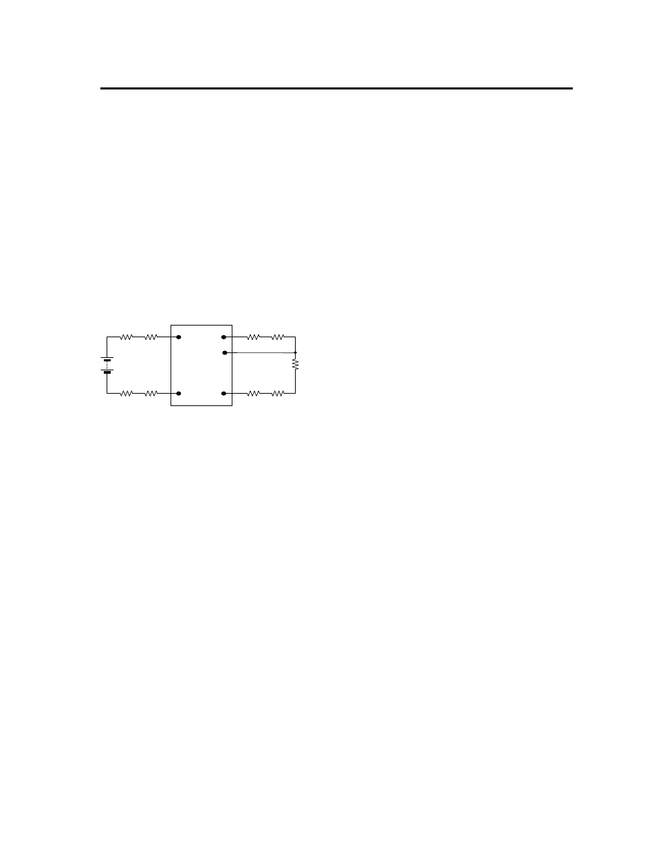
Remote Sense
The Austin SuperLynx
TM
SMT power modules have a
Remote Sense feature to minimize the effects of
distribution losses by regulating the voltage at the
Remote Sense pin (See Figure 32). The voltage between
the Sense pin and Vo pin must not exceed 0.5V.
The amount of power delivered by the module is defined
as the output voltage multiplied by the output current (Vo
x Io). When using Remote Sense, the output voltage of
the module can increase, which if the same output is
maintained, increases the power output by the module.
Make sure that the maximum output power of the module
remains at or below the maximum rated power. When
the Remote Sense feature is not being used, connect the
Remote Sense pin to the output pin.
V
O
C O M
V
IN
(+ )
C O M
R
LO A D
R
c ontact
R
distribution
R
c ontact
R
distribution
R
contac t
R
contac t
R
distribution
R
distribution
S ense
Figure 32. Remote sense circuit configuration