Feature description, Vout – GE Industrial Solutions Austin SuperLynx SMT User Manual
Page 12
Data Sheet
September 3, 2013
Austin Superlynx
TM
SMT Non-isolated Power Modules:
3.0 – 5.5Vdc input; 0.75Vdc to 3.63Vdc Output; 16A output current
LINEAGE
POWER
12
Feature Description
Remote On/Off
The Austin SuperLynx
TM
SMT power modules feature an
On/Off pin for remote On/Off operation of the module.
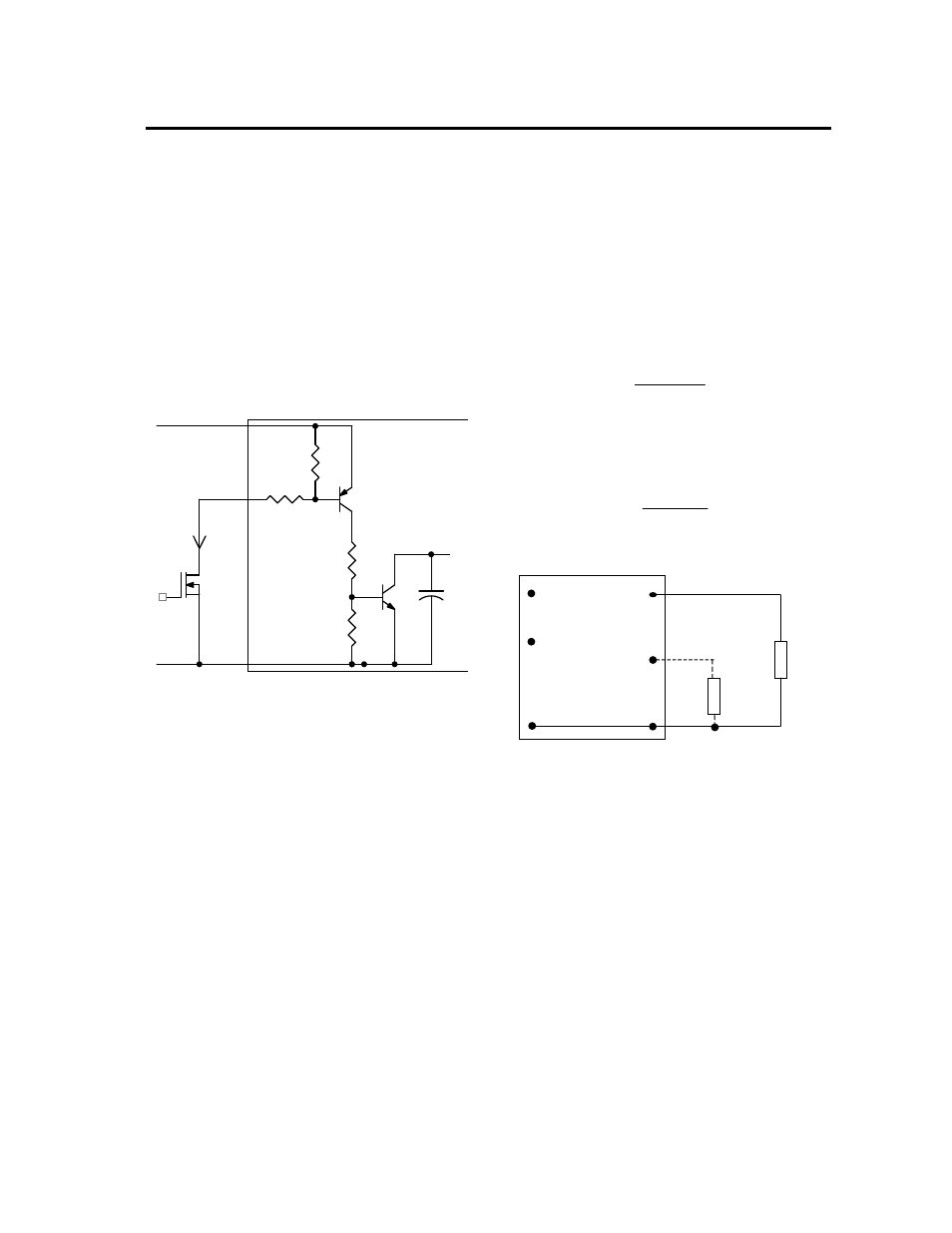
The circuit configuration for using the On/Off pin is shown
in Figure 28. The On/Off pin is an open collector/drain
logic input signal (Von/Off) that is referenced to ground.
During a logic-high (On/Off pin is pulled high internal to
the module) when the transistor Q1 is in the Off state, the
power module is ON. Maximum allowable leakage
current of the transistor when Von/off = V
IN,max
is 10µA.
Applying a logic-low when the transistor Q1 is turned-On,
the power module is OFF. During this state VOn/Off
must be less than 0.3V. When not using positive logic
On/off pin, leave the pin unconnected or tie to V
IN.
Q1
R2
R1
Q2
R3
R4
Q3
CSS
GND
VIN+
ON/OFF
PWM Enable
+
_
ON/OFF
V
I
ON/OFF
MODULE
Figure 28. Remote On/Off Implementation.
Overcurrent Protection
To provide protection in a fault (output overload)
condition, the unit is equipped with internal
current-limiting circuitry and can endure current limiting
continuously. At the point of current-limit inception, the
unit enters hiccup mode. The unit operates normally once
the output current is brought back into its specified range.
The typical average output current during hiccup is 3.5A.
Input Undervoltage Lockout
At input voltages below the input undervoltage lockout
limit, module operation is disabled. The module will begin
to operate at an input voltage above the undervoltage
lockout turn-on threshold.
Overtemperature Protection
To provide over temperature protection in a fault
condition, the unit relies upon the thermal protection
feature of the controller IC. The unit will shutdown if the
thermal reference point T
ref
, exceeds 125
o
C (typical), but
the thermal shutdown is not intended as a guarantee that
the unit will survive temperatures beyond its rating. The
module will automatically restart after it cools down.
Output Voltage Programming
The output voltage of the Austin SuperLynx
TM
SMT can
be programmed to any voltage from 0.75 Vdc to 3.63
Vdc by connecting a single resistor (shown as Rtrim in
Figure 29) between the TRIM and GND pins of the
module. Without an external resistor between TRIM pin
and the ground, the output voltage of the module is
0.7525 Vdc. To calculate the value of the resistor Rtrim
for a particular output voltage Vo, use the following
equation:
Ω
−
−
=
5110
7525
.
0
21070
Vo
Rtrim
For example, to program the output voltage of the Austin
SuperLynx
TM
module to 1.8 Vdc, Rtrim is calculated is
follows:
−
−
=
5110
7525
.
0
8
.
1
21070
Rtrim
Ω
=
k
Rtrim
004
.
15
V
O
(+)
TRIM
GND
R
trim
LOAD
V
IN
(+)
ON/OFF
Vout
Figure 29. Circuit configuration for programming
output voltage using an external resistor.
The Austin SuperLynx
TM
can also be programmed by
applying a voltage between the TRIM and the GND pins
(Figure 30). The following equation can be used to
determine the value of Vtrim needed to obtain a desired
output voltage Vo:
{
}
(
)
7525
.
0
1698
.
0
7
.
0
−
×
−
=
Vo
Vtrim
For example, to program the output voltage of a
SuperLynx
TM
module to 3.3 Vdc, Vtrim is calculated as
follows:
{
}
)
7525
.
0
3
.
3
1698
.
0
7
.
0
(
−
×
−
=
Vtrim
V
Vtrim
2670
.
0
=