GE Industrial Solutions Spectra Series Power Panelboards AMCB4GB and AMCB6GB User Manual
Page 3
5. Two-pole installations.
Use the following procedure
for all two-pole installations (kit AMCB4GB).
• For installations using phases A and B, continue
with step 5a.
• For installations using phases A and C, proceed to
step 5c.
• For installations using phases B and C, proceed to
step 5e.
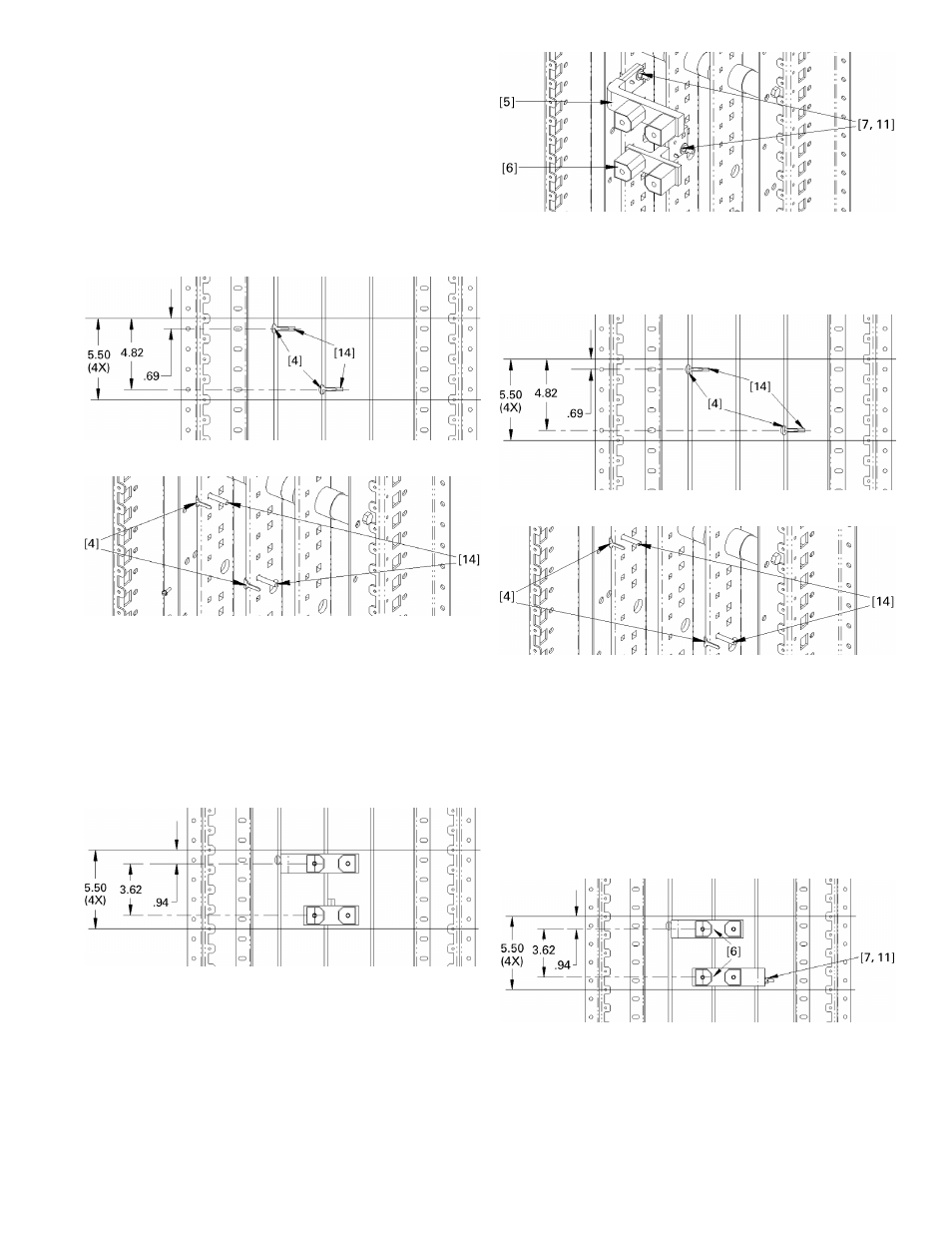
5a. Install carriage bolt assemblies on phases A and B.
Position the carriage bolt [14] and antiturn clip
[4] assemblies as shown in Figures 9 and 10.
Figure 9. Installing carriage bolt assemblies on phases A and B.
Figure 10. Installing carriage bolt assemblies on phases A and B,
isometric view.
5b. Install straps on phases A and B.
Place the G
frame straps [5, 6] over the carriage bolts and
antiturn clips, as shown in Figures 11 and 12.
Place conical washers [7] on the bolts and secure
with nuts [11]. Leave the connections finger tight.
If the group assembly selection is two-pole and the
assembly looks like Figure 12, then go to step 6.
Figure 11. Installing straps on phases A and B.
Figure 12. Installing straps on phases A and B, isometric view.
5c. Install carriage bolt assemblies on phases A and C.
Position the carriage bolt [14] and antiturn clip
[4] assemblies as shown in Figures 13 and 14.
Figure 13. Installing carriage bolt assemblies on phases A and C.
Figure 14. Installing carriage bolt assemblies on phases A and C,
isometric view.
5d. Install straps on phases A and C.
Place the G
frame straps [5] over the carriage bolts and
antiturn clips, as shown in Figures 15 and 16.
Place conical washers [7] on the bolts and secure
with nuts [11]. Leave the connections finger tight.
If the group assembly selection is two-pole and the
assembly looks like Figure 16, then go to step 6.
Figure 15. Installing straps on phases A and C.
Edge of G
Frame
Edge of G
Frame
Edge of G
Frame
Edge of G
Frame
Edge of G
Frame
Edge of G
Frame
Edge of G
Frame
Edge of G
Frame