GE Industrial Solutions Spectra Series Power Panelboards AMCB4GB and AMCB6GB User Manual
Page 2
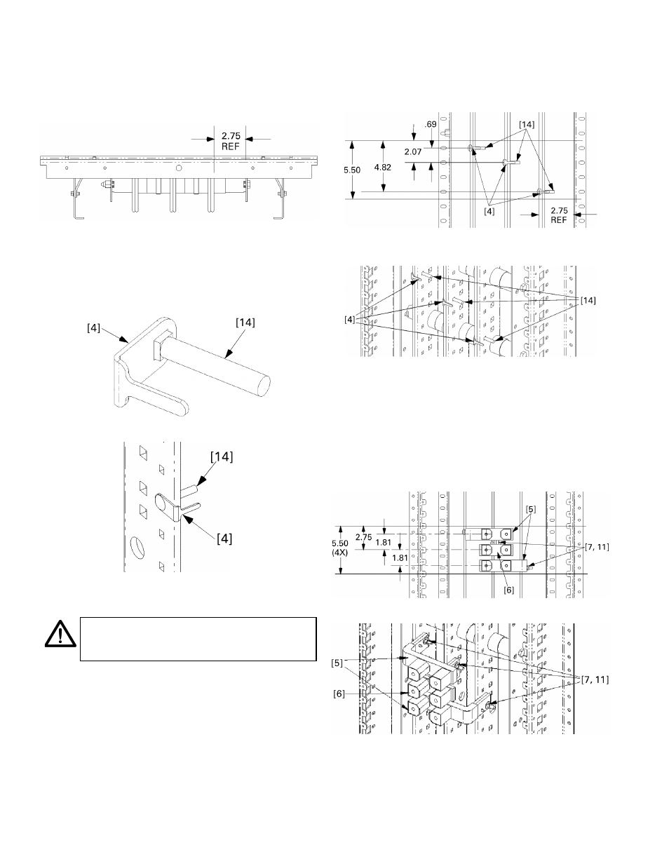
2. Locate the side of the interior with a 2.75-inch
reference distance.
The circuit breaker straps are
mounted on the side of the panel interior bus at
which the distance from the vertical bus face to the
inner face of the bus-support rail is 2.75 inches, as
indicated in Figure 2.
Figure 2. Illustration of the 2.75-inch reference distance.
3. Assemble antiturn clips onto carriage bolts.
Slide an
antiturn clip [4] over the square shank of each
carriage bolt [14], as shown in Figure 3. Figure 4
illustrates the installation of a bolt and antiturn clip
onto the interior, as called for in the remaining steps.
Figure 3. Assembling an antiturn clip [4] with a carriage bolt [14].
Figure 4. Installing a carriage bolt [14] and antiturn clip [4] into the
interior.
NOTE:
For three-phase installations, continue
with step 4. For two-pole installations, proceed
to step 5.
4. Three-phase installations.
Use the following procedure
for all three-phase installations (kit AMCB6GB).
4a. Install carriage bolt assemblies.
Position the
carriage bolt [14] and antiturn clip [4] assemblies
as shown in Figures 5 and 6.
Figure 5. Carriage bolt and antiturn clip installation for three-phase
connections.
Figure 6. Carriage bolt and antiturn clip installation for three-phase
connections, isometric view.
4b. Install straps.
Place the G frame straps [5, 6] over
the carriage bolts and antiturn clips, as shown in
Figures 7 and 8. Place conical washers [7] on the
bolts and secure with nuts [11]. Leave the
connections finger tight.
If the group assembly selection is three-phase and
the assembly looks like Figure 8, then go to step 6.
Figure 7. Installing the straps for three-phase connections.
Figure 8. Installing the straps for three-phase connections, isometric
view.
Edge of G
Frame
Edge of G
Frame
Edge of G
Frame
Edge of G
Frame