Product description, Step 1 – unpack and inspect – GE Industrial Solutions Record Plus TDM, NEMA 1, 3R, 12: FE250 User Manual
Page 2
DEH41025
Product Description
These instructions describe the installation
procedures for the rotary handle FENRH operating
mechanism accessory on
Record Plus
™ circuit
breakers, as illustrated in Figure 1.
The complete kits are available in the following
catalog number variants:
• FENRN provides the necessary parts for shallow
door mount of the handle on the breaker
mechanism through the enclosure door, with a
box depth of 5 29/32“ (150 mm), as shown in
Figure 1a. Maintain the dimension “H” [5
1/32” (127.8 MM)] as shown in Figure 12.
• FENRT is for mounting the handle and
operator in enclosures with variable depth, as
shown in Figure 1b. Maintain the dimension
“H” [Min 6 13/16“ inches (173 mm) and Max
15 inches (381.0 mm)] as shown in Figure 13.
In addition, the individual kit parts are available as
follows:
• FENRM1 consists of the operating mechanism
for shallow door mounts of the handle to the
breaker.
• FENRM3 consists of the operating mechanism
for extended shaft door mount of the handle.
• FENRH is the handle assembly only.
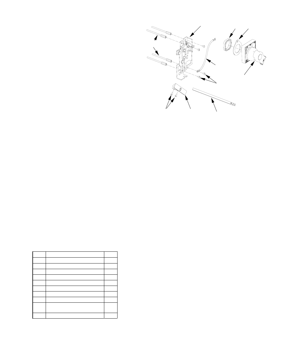
Step 1 – Unpack and Inspect
Unpack the rotary handle operating mechanism kit
and inspect the parts for any shipping damage.
Verify that all parts are supplied, as listed in Table 1.
The parts are illustrated in Figure 2.
Note that the numbers in brackets in the following
figures and installation instructions refer to the item
numbers in Table 1.
Item Description
Qty.
1
Screw, #10-32 X 3 5/32"
4
2 Base-crank
assembly
1
3 Grounding
wire
1
4
Screw, #10-32 x 1/2"
4
5 Nut,
plastic
1
6
Rotary handle assembly
1
7
Screw, #8-32 x 5/16"
4
8 Coupler
Assembly
1
9 Extension
shaft
assembly
1
10 Gasket
1
Table 1. List of parts included in the handle operator kits.
[1]
[2]
[3]
[4]
[5]
[10]
[8]
[6]
[7]
[9]
Figure 2. Parts supplied in the FENRH rotary handle kits.
Step 2 – Install the Breaker and
Handle Operating Mechanism
1.
Move the breaker handle to the OFF position.
2.
Mount the breaker to the enclosure with the # 10-
32 x 3 5/32" screws [1], as illustrated in Figure 3.
Tighten the screws to 27 - 32 in-lb.
Complete the
installation of the circuit breaker according to
installation instructions DEH40360.
3.
Place the base-crank assembly [2] on the breaker,
as illustrated in Figure 4. Insert four #10-32 x 1/2"
screws [4] through the mounting holes in the
base and into the heads of the breaker mounting
screws [1], with the grounding wire [3] attached
to one of the screws. Tighten the screws to 27 - 32
in-lb. Secure the other end of the grounding wire
to a suitable ground location.
4.
For kit FENRT variable-depth mounting only:
a. Measure the distance from the breaker-
mounting surface to the rotary handle-
mounting surface, H, as shown in Figures 8 &
13.
b. Cut the extension shaft [9] to the required
length “L” as illustrated in Figure 5.
c. Insert the shaft [9] upto 14 mm (35/64“ inch)
into the coupler [8] and secure it with #8-32 X
1/32“ screws [7], as illustrated in Figure 6.
Tighten the screws to 16 - 20 in-lb.
d. Place the shaft [9] assembled with coupler
[8] on to the crank of the base-crank assembly
[2] and secure with #8-32 x 5/16“ screws [7], as
illustrated in Figure 7. Tighten the screws to 16
- 20 in-lb.