GE Industrial Solutions EntelliGuard E Bell Alarm with Lockout for 800–2000 Ampere User Manual
Page 2
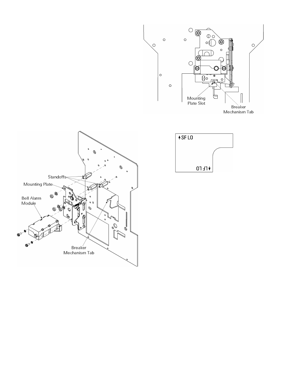
mechanism engages the slot in the bottom of the
mounting plate, as illustrated in the front view in
Figure 3.
7. Line up the Bell Alarm with Lockout module on the
mounting plate, as shown in Figure 2, so that the
solenoid plunger and locating pin fit in the
appropriate holes. The label on the end of the
module appears as in Figure 4, with the legend
↑
SF
LO
horizontal. Attach the module with the two screws
and bushings provided.
8. Run the wires from the Bell Alarm module to the
secondary disconnect, as illustrated in Figure 5.
Attach the wires to the breaker frame with wire ties as
indicated. Table 1 lists the wire colors and terminal
numbers. Figure 6 shows the secondary disconnect
terminal numbering scheme, as seen from the front
of the breaker, with the Bell Alarm terminals in bold.
Figure 2. Installing the Bell Alarm with Lockout.
Figure 3. Front view of the Bell Alarm with Lockout installation,
showing the breaker mechanism tab engaging the mounting plate slot.
Figure 4. Orientation of the label on the Bell Alarm with Lockout
module.
Returning the Breaker to Service
9. Check that the breaker racking mechanism is still in
the
DISC
position. Pull the manual charging handle
out part way, then slide the handle through the slot
in the escutcheon and move the escutcheon into
place. Insert the six mounting screws and tighten to
14–20 in-lb.
10. Replace the trim ring around the escutcheon, with
the narrow side at the bottom. Insert the ends of the
spring loaded rods into the holes in the escutcheon
brackets.
11. Insert the racking handle and return the racking
mechanism to the
DISC
position, as shown by the
draw-out position indicator.
12. Reinstall the breaker into its cubicle or substructure.