Applications above 250 v, C – wire terminal connections – GE Industrial Solutions Record Plus FG600 with SMR1 or SMR2 Trip Unit User Manual
Page 4
4
Applications Above 250 V
Because of safety considerations, a backplate must be attached
to the back of an FG breaker used in applications greater than
250 V. The backplate catalog number is listed in Table 6.
Table 6. Backplate used with applications above 250 V.
Mounting
Use Figure 4 as a reference to drill and tap all mounting holes
and make any necessary front panel escutcheon cut outs.
Mount the breaker using the appropriate breaker hardware kit,
listed in Table 7. Which includes four screws and lock washers.
Tighten the mounting screws to 20 lb-in.
Catalog
Number
Application Kit
Description
FGMSK1
Mounting plate with
tapped holes
Four #10-32 x 33/4
screws and lock
washers
FGMSK2
Mounting plate with
clearance holes
Four #10-32 x 41/4
screws, nuts, and lock
washers
Table 7. Breaker mounting kits.
Table 8. Lug catalog numbers and specifications
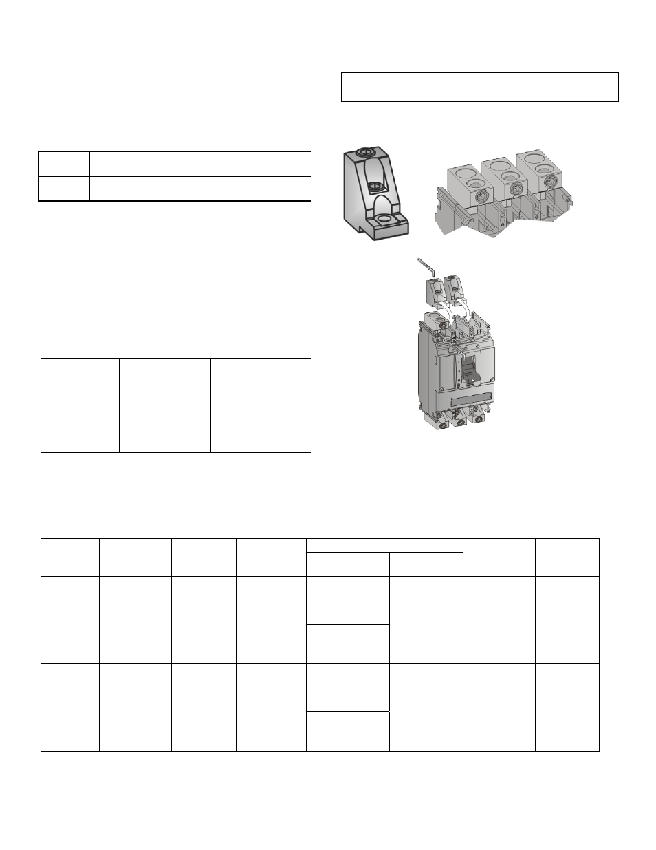
C – Wire Terminal Connections
NOTE: When using aluminum wire, use a joint compound
recommended by the wire manufacturer.
The lugs available for making wire connections to the breaker
are illustrated in Figure 3 and listed in Table 8.
Figure 3. Record Plus lug.
Catalog
Number
Application
Installation
Instructions
FGJB
Backplate for use with
applications above 250V
DEH40309
Catalog
Number
Wire Range
Dimension des
files
Wire Type
Location
Emplacement
Torque/Couple
Strip Length
Lug Material
Wire-Lug
Lug-Strap
FCALK218H
Top Hole
#8–400 kcmil
#6–500 kcmil
Bottom Hole
#2/0–600 kcmil
Copper
Aluminum
Copper or
Aluminum
2 Pole
(2 lugs)
#8–#4 AWG
AL/CU
275 in-lbs
200 in-lb
23 N-m
Top 7/8 in.
Bottom 15/8 in.
Tin-plated
aluminum
#3 AWG–600
kcmil AL/CU
375 in-lbs
FCALK318H
Top Hole
#8–400 kcmil
#6–500 kcmil
Bottom Hole
#2/0–600 kcmil
Copper
Aluminum
Copper or
Aluminum
3 Pole
(3 lugs)
#8–#4 AWG
AL/CU
275in-lbs
200 in-lb
23 N-m
Top 7/8 in.
Bottom 15/8 in.
Tin-plated
aluminum
#3 AWG–600
kcmil AL/CU
375 in-lbs