Section 5—operation, 1—general, 2—close spring charging – GE Industrial Solutions Power-Vac ML-20 Mechanism User Manual
Page 8: Figure 3 front view of powervac, Breaker without front cover, 3—closing operation (refer to figure 15)
8
SECTION 5—Operation
5.1—General
The PowerVac
®
vacuum circuit breaker uses sealed vacuum
power interrupters to establish and interrupt a primary circuit.
Primary connections to the associated metalclad switchgear
are made by horizontal bars and disconnect fingers, electrically
and mechanically connected to the vacuum interrupters.
Molded interrupter supports, one per phase on a three-phase
circuit breaker, provide mountings for the primary bars,
interrupters, current transfer fingers, and heat dissipation fins
(where used). The operating mechanism provides direct
motion at each phase location in order to move the lower
contact of the vacuum interrupters from an open position to a
spring-loaded closed position and then back to the open
position on command.
The ML-20 mechanism (Figure 15) is of the stored-energy
type and uses a gearmotor to charge a closing spring. During
a closing operation, the energy stored in the closing spring is
used to close the vacuum interrupter contacts, compress the
wipe springs which load the contacts, charge the opening
spring, and overcome bearing and other friction forces, The
energy then stored in the wipe springs and opening spring will
open the contacts during an opening operation.
Closing and opening operations are controlled electrically by
the metalclad switchgear or remote relaying. Mechanical
control is provided by manual close and trip buttons on the
circuit breaker. The closing spring may be manually charged,
and a method for slow-closing the primary contacts is
available. The mechanism will operate at the ac or dc voltage
indicated on the circuit breaker nameplate.
5.2—Close Spring Charging
Figure 15 shows a front view of the ML-20 in a schematic
form. The primary contacts are open and the closing spring is
charged. The closing spring charging system consists of a
closing spring (1, view B) mounted on the left side of the
breaker and the electrical charging system mounted on the
right side of the breaker. Both components are fastened to
the cam shaft (2, view B). A manual charging system (3, view
A) is provided so that the mechanism can be slow closed and
the closing spring can be charged without electrical control
power.
Spring charging is accomplished electrically by a rotating
eccentric on the output shaft of the gear motor driving pivoted
charging arms (4, view C) which oscillate about the centerline
of a ratchet wheel (5, view C). A driving pawl (6, view C),
mounted within the charging arms, oscillates with the
charging arms. Starting from its rear-most position, as the
charging arms rotate forward, a spring forces engagement of
the driving pawl with a tooth of the ratchet wheel. The ratchet
wheel is advanced by the rotating charging arms and pawl
assembly. Advancement of one tooth spacing is provided for
each oscillation of the system. The ratchet motion is restricted
to one direction by a spring-loaded holding pawl that prevents
the ratchet wheel from going backwards as the charging arms
oscillate back to pick up the next tooth. Thirteen complete
cycles of the charging arms are needed for a full charge of the
closing spring. The efficient, compact gear motor
accomplishes this action in about three seconds. When the
charging cycle is complete, the ratchet wheel is positioned so
that three missing teeth adjacent to the driving pawl and any
motor overspin will not drive the ratchet wheel, thus
preventing damage to the system.
When the spring is completely charged, the assembly is
retained in that position by the close latch, until it is desired
to close the circuit breaker.
The closing coil cannot be electrically energized unless the
closing spring is completely charged. This action is prevented
by the 52/CHG switch in the closing circuit.
The manual charging system (3, view A) works directly on the
cam shaft where a one-way clutch (7, view A), driven by a
manual handle, provides rotation of the ratchet wheel. Manual
pumping of the handle advances the ratchet wheel and the
holding pawl prevents counter-rotation while the handle is
returning for another stroke. Approximately eight complete
strokes of the manual handle are required for one complete
spring-charging operation. When the spring charge indicator
(9, Figure 3) shows “CHARGED”, MANUAL CHARGING MUST
BE DISCONTINUED TO AVOID MECHANISM DAMAGE.
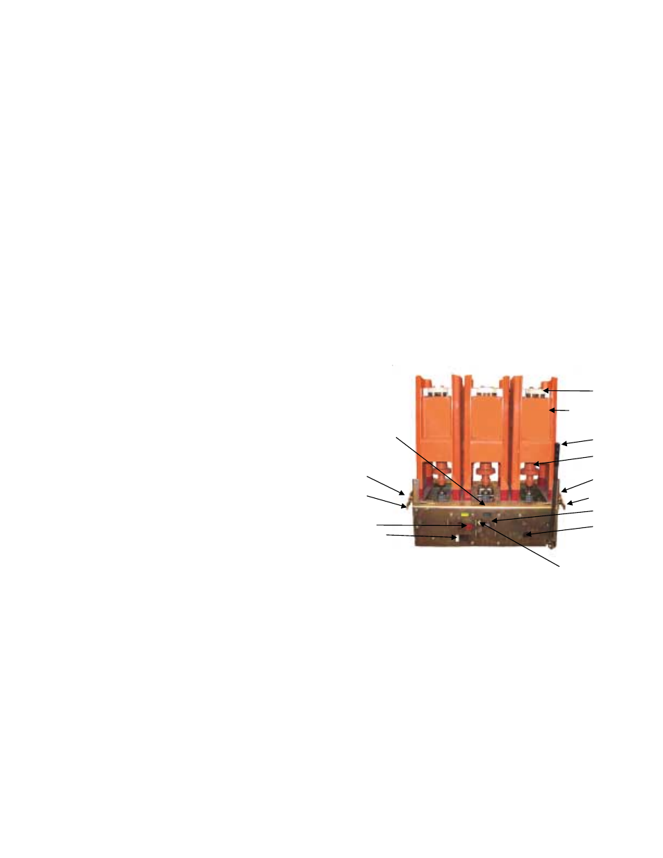
Figure 3 Front view of PowerVac
®
breaker
without front cover
1. Upper interrupt connection 8. Counter
2. Interrupter support
9. Spring charge indication
3. Operating rod
10. Manual charge lever
4. Racking arm
11. Manual close button
5. Compartment track rollers 12. Test position handle for
6. Manual trip button
secondary disconnects
7. Open/Close indicator
13. Closing spring gag access
5.3—Closing Operation
(refer to Figure 15)
By either energizing the close solenoid or depressing the
manual close button, the close latch (8, view C) is rotated,
releasing the closing spring (1, view B). This action releases
the energy in the closing spring and transmits it to the closing
cam (9, view D) and closing roller (10, view D) and causes
1
12
2
3
4
5
10
11
8
13
9
6
9
7
5
4