GE Industrial Solutions Power-Vac ML-20 Mechanism User Manual
Page 12
12
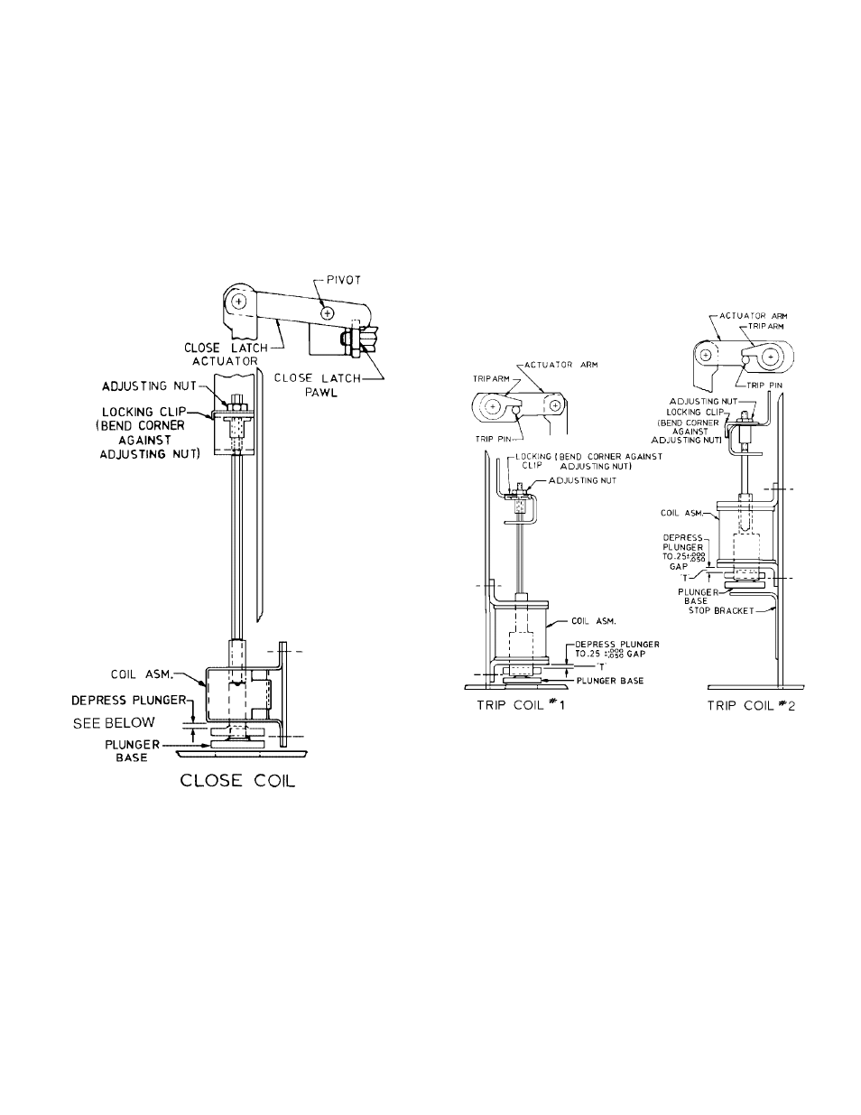
8.4—Close Coil Plunger Gap
The close coil plunger gap is shown in Figure 8. With the
closing spring discharged, operate the plunger to make certain
that the plunger moves freely over its full stroke in the coil. To
check the closing coil plunger gap the breaker should be open
and the closing spring charged and gagged. Depress the close
plunger button until resistance is felt. The gap between the
plunger button and the coil housing should be as follows:
Figure 8 Close coil plunger gap
8.5—Trip Coil Plunger Gap
The trip coil plunger gap is shown in Figure 9. With the
breaker in the open position and the closing spring in the
charged position, make certain that the trip linkage and trip
shaft move freely over the full plunger travel. To check the trip
coil plunger gap adjustment, the breaker is to be closed with
the closing spring discharged. Dimension T between the
plunger button and the coil housing should be between 0.20
and 0.25 inch. This dimension is obtained when the trip
plunger button is depressed until resistance is felt. If the
breaker is equipped with an optional second trip coil, use
same procedure.
Figure 9 Trip coil plunger gap
8.6—Control Switch Adjustment
The breaker is to be in the open position with the opening and
closing springs discharged. This results in the control switch
plungers being in the depressed position. The switches to be
checked are shown in Figure 10. On the LCS and stacked
switches (SM/LS & CHG), the plunger rod is to be recessed
within the rear of the switch body and this recess is to be 0 to
1/32 inch. This is a visual check. No adjustment is required on
the CL/MS or the IL/MS.