GE Industrial Solutions Power-Vac ML-20 Mechanism User Manual
Page 10
10
Figure 5 Gag plate installation
1 Closing spring gag plate
2 Manual charging lever
7.3—Closing Spring Gag
Insert the closing spring gag plate (1, Figure 5) by opening the
closing spring gag hole cover and inserting the tip of the gag
plate between the end of the spring and the spring guide and
engaging the détentes on the gag plate into the slots in the
closing spring guide. Note that when the closing spring guide
is exposed for gagging, an interference angle is exposed on
the left side of the breaker (1, Figure 17). With the closing
spring in the gagged position, this angle will provide
interference preventing use of the lift truck and racking of the
breaker element. No attempt should be
made to alter, modify or otherwise make inoperative this
safety feature. With the gag plate in position, depress the
manual close button. This action will partially discharge the
closing spring and also partially close the vacuum interrupter
contacts. Do not energize the secondary control circuit at this
time.
7.4—Slow Closing
To manually slow close the breaker contacts, install the
closing spring gag, as described above, and push the manual
close button (11, Figure 3). Then put the manual charge
handle on the manual charge lever and move the handle up
and down. The breaker will be fully closed when the spring
charge indicator shows “CHARGED”.
CAUTION: WITH THE GAG PLATE INSTALLED, THE
BREAKER CLOSED, AND OPENING SPRINGS CHARGED, THE
BREAKER CAN BE TRIPPED AT FULL SPEED.
7.5—Gag Plate Removal
To remove the gag plate, the closing spring must be fully
charged. If the spring charge indicator does not show
“CHARGED” in the window, manually charge the spring until
it does. Lift up and push in on the gag plate to clear the
détentes on the gag plate from the slots in the closing spring
guide. While holding the gag plate up, remove it from the
opening. Close the gag hole cover. For safety, first close the
breaker by depressing the manual “CLOSE” button and then
depress the manual “TRIP” button. All stored energy is now
removed from the breaker.
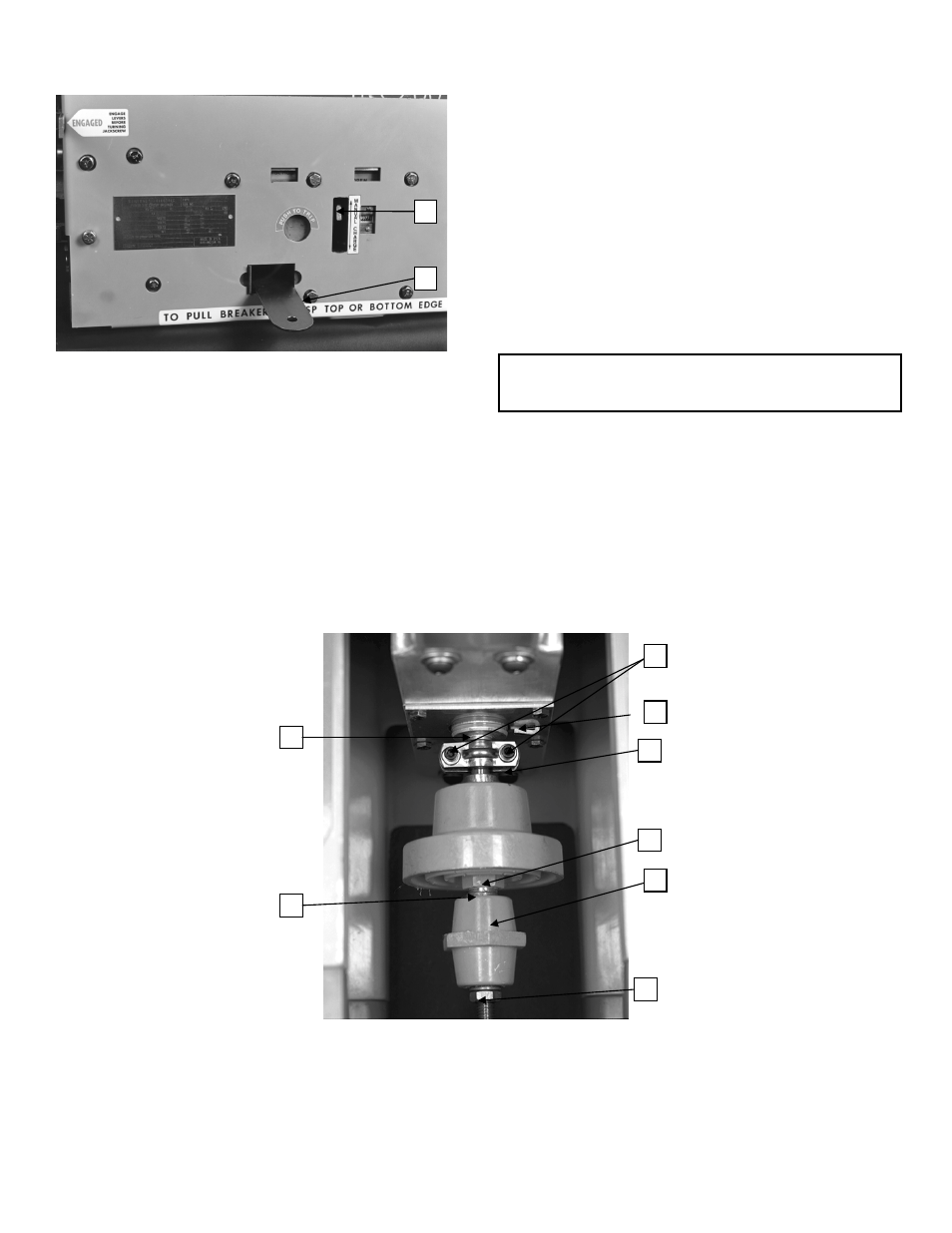
Figure 6 Operating rod assembly
1. Erosion Marker
4. Hexagon projection
7. Clamp screws
2. Lock nut
5. Operating rod insulator
8. Interrupter movable contact rod
3. Lock washer
6. Coupling clamp
2
1
8
7
6
5
4
3
2
1