Data sheet, Surface mount information – GE Industrial Solutions EHHD006A0B Hammerhead Series User Manual
Page 12
GE
Data Sheet
EHHD006A0B Hammerhead Series; DC-DC Converter Power Modules
18-75Vdc Input; 12Vdc, 6.0A, 72W Output
July 12, 2013
©2012 General Electric Company. All rights reserved.
Page 12
Surface Mount Information
(continued)
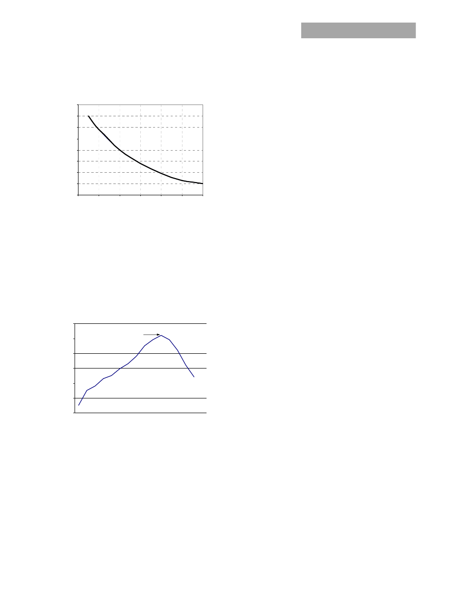
MAX TEMP
SO
LDE
R
(
C)
Figure 24. Time Limit Curve Above 205
o
C for Tin/Lead
(Sn/Pb) process
Pb-free Reflow Profile
Power systems will comply with J-STD-015 Rev. C
(Moisture/Reflow Sensitivity Classification for Nonhermetic
Solid State Surface Mount Devices) for both Pb-free solder
profiles and MSL classification procedures. This standard
provides a recommended forced-air-convection reflow
profile based on the volume and thickness of the package
(table 4-2). The suggested Pb-free solder paste is Sn/Ag/Cu
(SAC). The recommended linear reflow profile using
Sn/Ag/Cu solder is shown in Figure 25.
Figure 25. Recommended linear reflow profile using
Sn/Ag/Cu solder.
Post Solder Cleaning and Drying Considerations
Post solder cleaning is usually the final circuit board
assembly process prior to electrical board testing. The result
of inadequate cleaning and drying can affect both the
reliability of a power module and the testability of the
finished circuit board assembly. For guidance on
appropriate soldering, cleaning and drying procedures, refer
to GE Board
Mounted Power Modules: Soldering and Cleaning Application
Note (AN04-001).
200
205
210
215
220
225
230
235
240
0
10
20
30
40
50
60
Per J-STD-020 Rev. C
0
50
100
150
200
250
300
Reflow Time (Seconds)
R
efl
o
w
T
em
p
(°
C
)
Heating Zone
1°C/Second
Peak Temp 260°C
* Min. Time Above 235°C
15 Seconds
*Time Above 217°C
60 Seconds
Cooling
Zone