GE Industrial Solutions Record Plus For use with FB100, FC100,FE250, and FG600 User Manual
Record plus, Molded case circuit breaker accessories, Product description
DEH40324 Installation Instructions
g
Record Plus™
Molded Case Circuit Breaker
Accessories
Auxiliary and Bell Alarm Switches
Congratulations and thank you for choosing the
Record Plus™
family of current-limiting circuit
breakers. These UL-listed auxiliary and bell alarm
switches are suitable for use with the FB100, FC100,
FE150, FE250, FG400, and FG600 circuit breaker
series.
Record Plus™
circuit breakers are designed with a
full line of integrated accessories. All units use the
latest in integrated modular circuit breaker
technology for flexibility in application and
maximizing the product’s utilization and
capabilities.
Record Plus™
circuit breakers are all listed by
Underwriters Laboratories to the UL489 standard
and may be listed to CSA Standard C22.2, No. 5
and IEC60947-2.
They can also be used with our molded case
switches, which are listed per Underwriters
Laboratories to the UL489 standard.
Record Plus™
circuit breakers and their accessories
are designed and manufactured to exceed our
global customers’ high standards for reliability and
quality.
WARNING
: DANGER of electrical shock or injury.
Ensure that ALL electrical power supplies are OFF
before installing or removing any devices. The
breaker, trip unit, or accessories MUST ONLY be
installed and serviced by QUALIFIED personnel. See
NEMA publication AB4.
AVERTISSEMENT: Danger contre les risques
d'électrocutions. S'assurer avant TOUTES
manipulations du disjoncteur que les différentes
sources d'alimentation sont en position OFF. Les
disjoncteurs, unités de protection, ou accessoires
doivent être installés par des personnes qualifiées et
habilitées. Lira NEMA publication AB4.
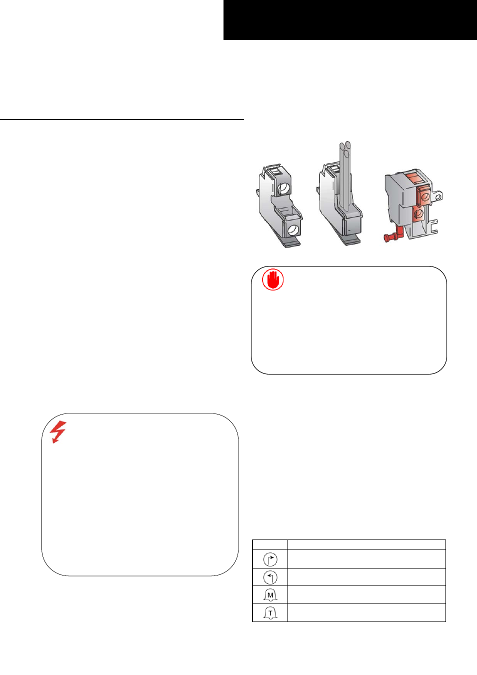
Figure 1. Bell alarm and auxiliary switches.
CAUTION: This product is NOT suitable for use in
equipment not specifically design to accept it.
Contact the equipment manufacturer for possible
equipment modifications.
ATTENTION: Cet appareil nedoit pas etre employe
dans un equipement non specialement adapte a cet
effet. Contactez le constructeur concernant les
possibles modifications a apporter a l'equipement.
Product Description
The auxiliary and bell alarm switches covered by these
instructions are illustrated in Figure 1. A key for the
different symbols used in these instructions is found in
Table 1. Catalog numbers for the various switch
configurations are listed in Table 2.
Note that contact position for the auxiliary switch is
shown with the breaker in the open position. Bell alarm
contact position is shown with the breaker in the
untripped position.
Mechanical-trip bell alarms are activated by the trip unit
(overcurrent or short circuit), undervoltage release,
shunt trip, or push-to-trip button. Overcurrent/short-
circuit trip bell alarms are activated by the trip unit only
and are not available for FB and FC breakers.
Symbol Description
Right-hand pocket auxiliary switch
Left-hand pocket auxiliary switch
Mechanical-trip bell alarm (all tripping
functions)
Overcurrent / short-circuit trip bell alarm
(not available on FC breakers)
Table 1. Key to symbols.