GE Industrial Solutions Spectra G-Frame MCCB with microEntelliGuard trip unit User Manual
Page 4
GEH-700 Installation Instructions
For individual front panel mounting:
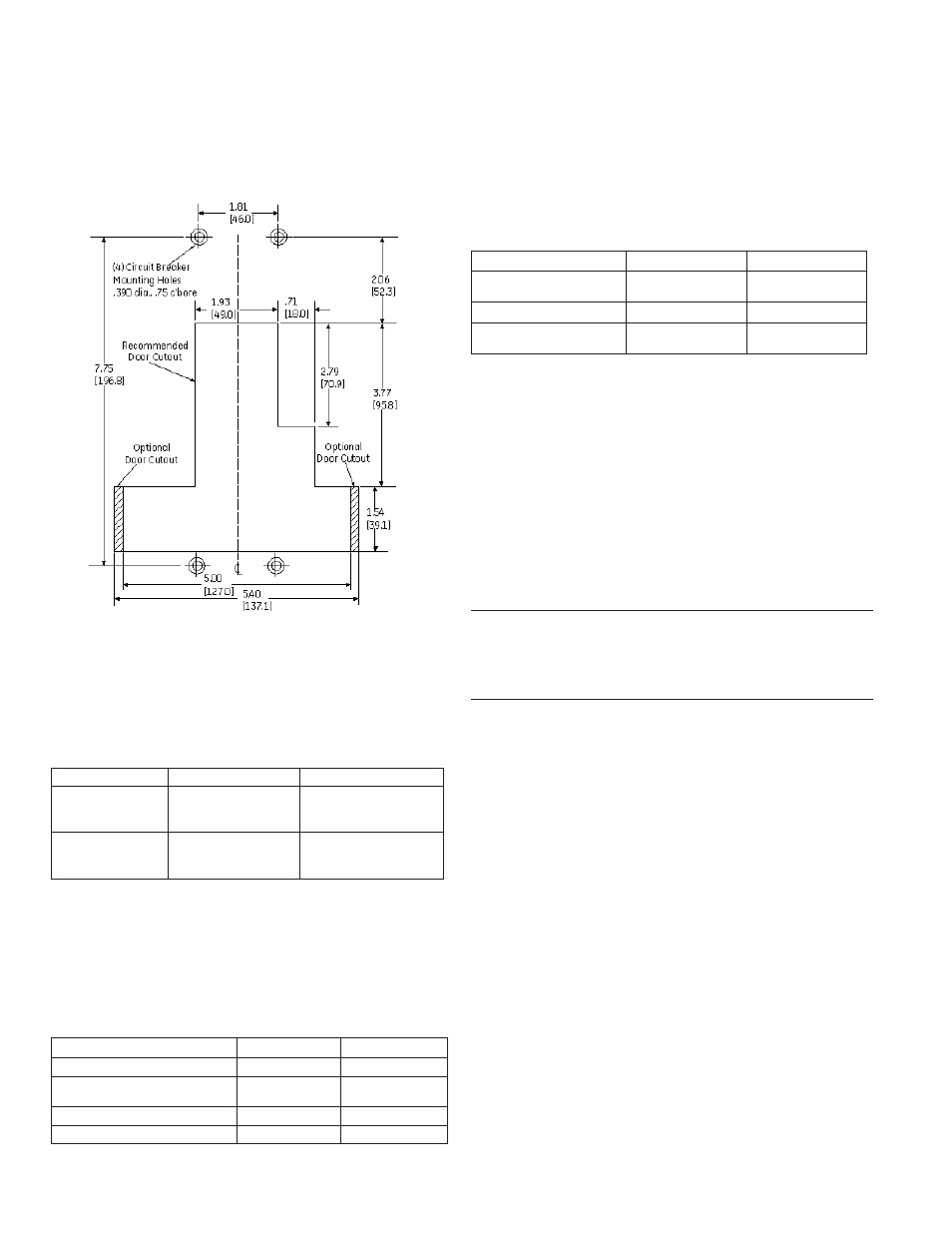
1. Drill and tap all mounting holes and make any
necessary front-panel escutcheon cutouts, as
shown in Figure 1.
Figure 1. Mounting Hole and Escutcheon Cutout Pattern in/(mm)
2. Mount the breaker with the hardware described in
Table 5, following the instructions supplied with the kit.
Table 5. Breaker Mounting Screw Kits
Catalog Number Application
Kit Description
SFGMSK1
Mounting plate with
tapped holes
Four #12-24x3-3/4
screws and lock
washers
SFGMSK2
Mounting plate with
clearance holes
Four #12-24x4-1/4
screws, nuts, and lock
washers
For GE switchboard and panelboard mounting:
Install the breaker into the equipment according to the
instructions supplied with the equipment. Available
mounting hardware kits are listed in Table 6.
Table 6. Equipment Mounting Hardware Kits
Equipment
Double Branch Single Branch
Panelboard-Spectra Series
AMC6GBFP
AMC3GMFP
Switchboard – Spectra Series
class 1 and 2
AMC6GBFP
AMC3GMFP
Switchboard – AV1, AV2
N/A
N/A
Switchboard – AV3, AV5
N/A
ContactFactory
For individual mounting in a GE enclosure:
Install the breaker according to the instructions
supplied with the enclosure. Available enclosures
are listed in Table 7 (refer to the BuyLog for other
accessories and/or any enclosure limitations).
Table 7. Enclosures
Enclosure Type
400A Catalog No. 600A Catalog No.
NEMA 1 (indoor)
SG400F
SG400S
SG600F
SG600S
NEMA 3R (outdoor)
SG400R
SG600R
NEMA 12 (oil-tight and
dust-tight)
SG400J
SG600J
Setup and Adjustment
The Spectra RMS microEntelliGuard
TM
trip units are
digital, rms sensing, electronic trip units with an LCD
and keypad for viewing and/or changing the various
function settings. Refer to User’s Manual GEH-702
for detailed information concerning the operation,
adjustment, and setting of the breaker trip unit.
You should record the overcurrent protection and
protective relay set points for future reference.
NOTE: Trip units as received may have settings that are
undesirable for the specific application. Ensure that
settings are appropriately adjusted before energizing
the breaker.
Operation
The circuit breaker status is indicated by ON/OFF
markings, universal I/O symbols, and an indicator
window that shows red for ON, yellow for TRIP, and
green for OFF. The corresponding handle positions are
illustrated in Figure 2. To close the breaker from the
OFF position, move the handle to the ON position. To
close the breaker from the TRIP position, first move the
handle to the OFF (reset) position, and then back to the
ON position.
A Push-To-Trip button is provided for convenience in
testing the mechanical operation of the breaker.