GE Industrial Solutions Spectra G-Frame MCCB with microEntelliGuard trip unit User Manual
Page 3
GEH-700 Installation Instructions
3. Install any internal accessories, following the
instructions supplied with each accessory. Available
accessories and their mounting locations are
listed in Table 3. Check all accessories for proper
installation and wire routing. Verify breaker
operation with the installed accessories. Accessory
leads can be routed along the side of the breaker
and across the back. An auxiliary switch is required
for the breaker status signal.
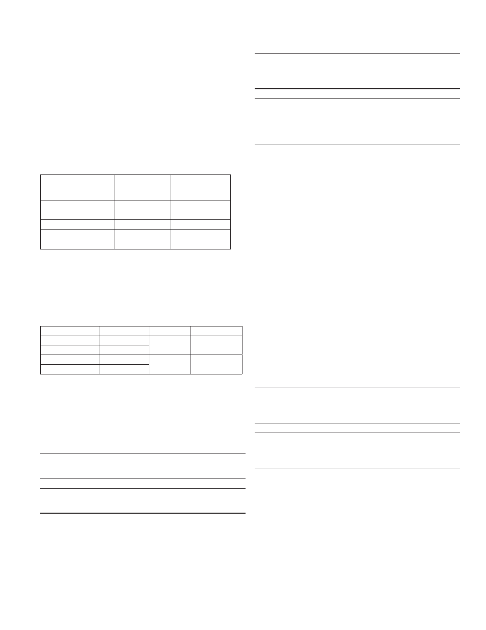
Table 3. Internal Accessories
Internal Accessory
Maximum
Number of
Accessories
Accessory
Installation
Location
Auxiliary Switch
(SPDT or DPDT)
1
Right
Bell Alarm Switch
1
Left
Shunt Trip or
Undervoltage Release
1
Left
4. Attach the terminal lugs, listed in Table 4, following the
instructions supplied with the lug kit. Use one kit for
either line or load end; two kits are required for both.
Table 4. Available Lug Kits
Catalog Number Description
Wire Type
Lug Material
TCLK265
2 Pole Lug Kit
Cu/Al
Tin-plated
Aluminum
TCLK365
3 Pole Lug Kit
TCOK265
2 Pole Lug Kit
Cu only
Tin-plated
Copper
TCOK365
3 Pole Lug Kit
5. Ensure that all terminals are torqued to the proper
value, as listed in the lug kit instruction sheet. Install
the terminal covers, ensuring that they are firmly
seated.
NOTE: Aluminum wire must be used with a joint
compound recommended by the wire manufacturer.
IMPORTANT: Si un cable en aluminum est employé,
utilisez le lubrifiant recommandé par le fabricant.
WARNING: It is important that the terminal covers are
installed correctly to ensure proper circuit breaker
operation.
IMPORTANT: Il est important de vérifier que tous
couvercles ou caches de protection sont correctement
installés afin d’assurer le bon fonctionnement de
l’appareil.
6. Finally, connect all associated components that are
required for the breaker to function properly, using
the instructions supplied with each component.
The following is a list of available associated
components:
• Terminal board connector
• Neutral current sensor connector
• Control power connector
• Extension cable
• Control power module (control power transformer
may be required)
• Voltage conditioners (potential transformers may
be required)
• Voltage module
• Neutral current sensor
Mounting
All Spectra
®
RMS circuit breakers are suitable for
reverse feed and have no line or load markings.
Incoming power cables or busbars may be connected
to either the upper or lower terminals as required by
the application.
WARNING: Danger of electrical shock or injury. Turn
OFF the power ahead of equipment before installing
this device or removing any other device.
IMPORTANT: Danger de choc électrique ou de blessure.
Couper l’alimentation entrant dans l’appareil avant de
monter celui-ci ou de démonter d’autres appareils.