Component removal, Trip, Unit removal – GE Industrial Solutions ProTrip Conversion Kits AK-1-15 and AK-1-25 User Manual
Page 5: Removing the trip unit coil connections, Disassembled, Ak-1-25 breaker
SECTION 3. DISASSEMBLING THE
BREAKER
GE Type AK-1 breakers need not have their front and
back frames separated for installation of the
conversion kit. The procedure is to remove the old
electromechanical trip units, then install the kit.
First, remove the breaker from its compartment and
place it on a clean, well-lighted workbench in an
upright position, so that both the front and back are
easily accessible.
Component Removal
1. Remove and save the load terminal primary dis-
connect fingers on all draw-out breakers. They
are held in place with a
1
/
4
-20 bolt, as shown in
Figure 1.
2. Remove and discard the two screws on each side
of the EC trip units, shown in Figure 2, that hold
the covers in place.
3. Remove and discard the Philips-head screw
above each EC trip unit. It may be necessary to
remove the left and right trip paddles. The trip
paddles may be discarded.
4. Remove and discard the two
5
/
16
-inch Allen-head
bolts holding the trip unit coils to the breaker
frame.
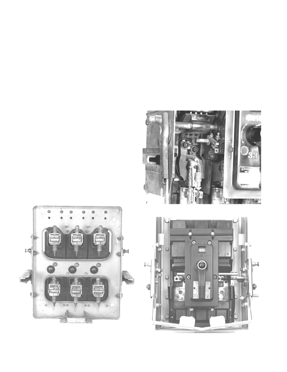
5. Remove and discard the three electromechanical
trip units. The disassembled breaker is shown in
Figure 4.
Figure 1. Draw-out primary disconnect fingers.
Figure 2. EC trip unit removal.
Figure 3. Removing the trip unit coil connections.
Figure 4. Disassembled AK-1-25 breaker.
6