Flux, Shifter adjustment, Wiring – GE Industrial Solutions ProTrip Conversion Kits AK-1-15 and AK-1-25 User Manual
Page 11: Harness installation
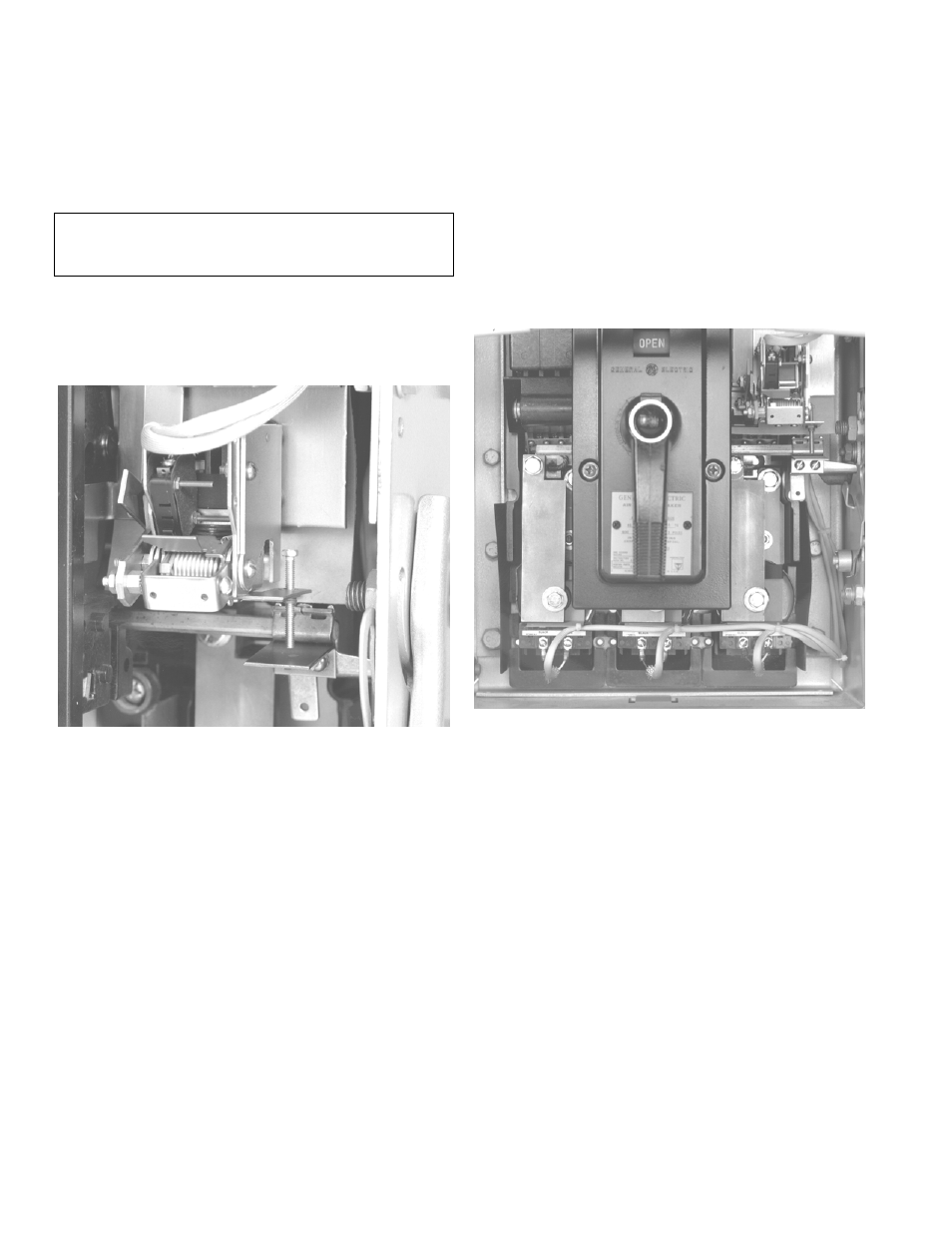
Adjusting the Flux Shifter
With the breaker in the CLOSED position, the gap
between the adjustment screw and the trip paddle
should be
1
/
16
inch, as shown in Figure 15. For safety,
OPEN the breaker to adjust the screw with a
1
/
4
-inch
wrench.
WARNING:
Be extremely careful when working on a
closed breaker.
Do not
reach into the mechanism
while adjusting the flux shifter.
12
Optional Test
– The flux shifter may be tested by
closing the breaker and applying a 9 Vdc power
source to the flux shifter leads (the red wire is posi-
tive). The breaker should trip.
Figure 15. Flux shifter adjustment.
Connecting the Trip Unit Wiring Harness
1. Join the four-pin connector on the trip unit har-
ness to the four-pin connector on the flux shifter.
2. Connect the harness leads to the screw terminals
on each CT, as shown in Figure 16. The black wire
(tap) connects to the left terminal and the white
wire (common) to the right terminal.
3. Use the wire ties provided to tie the harness back
against the frame. The harness should be tied to
the holes in the fiber barriers at each CT. Ensure
that the wiring will not interfere with any moving
parts.
Figure 16. Wiring harness installation.