Test configurations, Austin superlynx ii, Lineage power 9 – GE Industrial Solutions ATM020A0X3-SR User Manual
Page 9: Figure 16. output ripple and noise test setup
Data Sheet
September 10, 2013
Austin SuperLynx II
TM
SMT Non-isolated Power Modules:
2.4 – 3.63Vdc input; 0.75Vdc to 2.0Vdc Output; 20A output current
LINEAGE
POWER
9
Test Configurations
TO OSCILLOSCOPE
CURRENT PROBE
L
TEST
1μH
B
A
TTE
R
Y
C
S
1000μF
Electrolytic
E.S.R.<0.1
Ω
@ 20°C 100kHz
2x100μF
Tantalum
V
IN
(+)
COM
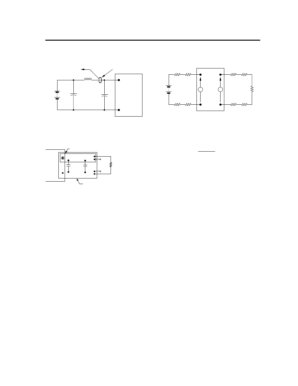
NOTE: Measure input reflected ripple current with a simulated
source inductance (L
TEST
) of 1μH. Capacitor C
S
offsets
possible battery impedance. Measure current as shown
above.
C
IN
Figure 15. Input Reflected Ripple Current Test Setup.
NOTE: All voltage measurements to be taken at the module
terminals, as shown above. If sockets are used then
Kelvin connections are required at the module terminals
to avoid measurement errors due to socket contact
resistance.
V
O
(+)
COM
1uF
.
RESISTIVE
LOAD
SCOPE
COPPER STRIP
GROUND PLANE
10uF
Figure 16. Output Ripple and Noise Test Setup.
V
O
COM
V
IN
(+)
COM
R
LOAD
R
contact
R
distribution
R
contact
R
distribution
R
contact
R
contact
R
distribution
R
distribution
V
IN
V
O
NOTE: All voltage measurements to be taken at the module
terminals, as shown above. If sockets are used then
Kelvin connections are required at the module terminals
to avoid measurement errors due to socket contact
resistance.
Figure 17. Output Voltage and Efficiency Test Setup.
η =
V
O
. I
O
V
IN
. I
IN
x
100
%
Efficiency