Electrical specifications, Austin superlynx ii, Continued) – GE Industrial Solutions ATM020A0X3-SR User Manual
Page 3
Data Sheet
September 10, 2013
Austin SuperLynx II
TM
SMT Non-isolated Power Modules:
2.4 – 3.63Vdc input; 0.75Vdc to 2.0Vdc Output; 20A output current
LINEAGE
POWER
3
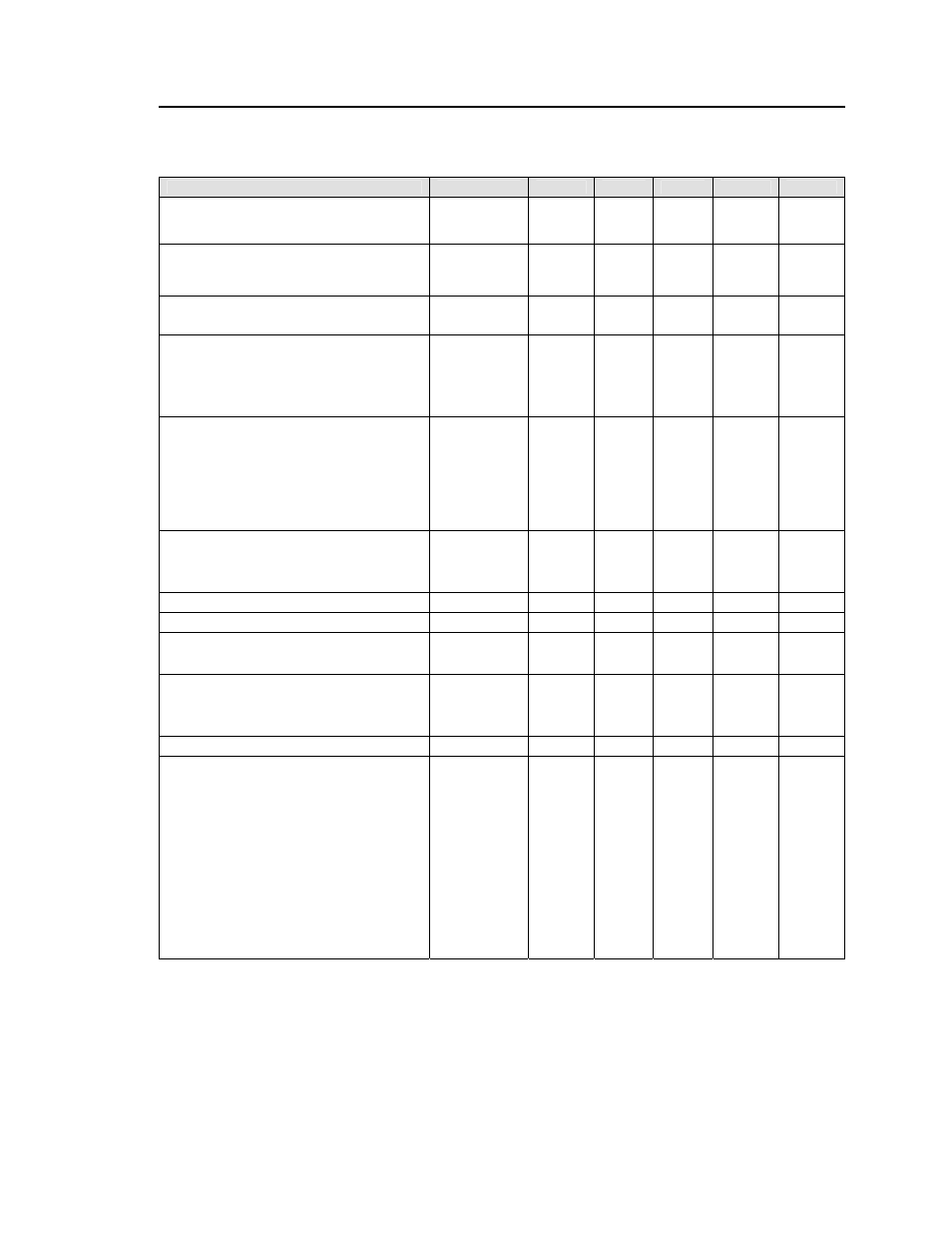
Electrical Specifications
(continued)
Parameter
Device
Symbol
Min
Typ
Max
Unit
Output Voltage Set-point
All
V
O, set
–2.0
⎯
+2.0 %
V
O, set
(V
IN
=
IN, min
, I
O
=I
O, max
, T
A
=25°C)
Output Voltage
All
V
O, set
–3%
⎯
+3% %
V
O, set
(Over all operating input voltage, resistive load,
and temperature conditions until end of life)
Adjustment Range
All
V
O
0.7525
2.0 Vdc
Selected by an external resistor
Output Regulation
Line (V
IN
=V
IN, min
to V
IN, max
) All
⎯
0.3
%
V
O, set
Load (I
O
=I
O, min
to I
O, max
) All
⎯
0.4
%
V
O, set
Temperature (T
ref
=T
A, min
to T
A, max
) All
⎯
0.4
%
V
O, set
Output Ripple and Noise on nominal output
(V
IN
=V
IN, nom
and I
O
=I
O, min
to I
O, max
Cout = 1μF ceramic//10μFtantalum capacitors)
RMS (5Hz to 20MHz bandwidth)
All
⎯
8 15
mV
rms
Peak-to-Peak (5Hz to 20MHz bandwidth)
All
⎯
25 50
mV
pk-pk
External Capacitance
ESR ≥ 1 mΩ All
C
O, max
⎯
⎯
1000
μF
ESR ≥ 10 mΩ All
C
O, max
⎯
⎯
5000
μF
Output Current
All
I
o
0
⎯
20 Adc
Output Current Limit Inception (Hiccup Mode )
All
I
O, lim
⎯
180
⎯
% I
o
Output Short-Circuit Current
All
I
O, s/c
⎯
3.5
⎯
Adc
(V
O
≤250mV) ( Hiccup Mode )
Efficiency V
O,set
= 0.75Vdc
η
77.5
%
V
IN
= 2.4V, T
A
=25°C V
O, set
= 1.2Vdc
η
83.5
%
I
O
=I
O, max ,
V
O
= V
O,set
V
O,set
= 1.8Vdc
η
89.0
%
Switching Frequency
All
f
sw
⎯
300
⎯
kHz
Dynamic Load Response
(dI/dt=2.5A/
μs; V
IN
= V
IN, nom
; T
A
=25°C)
All V
pk
⎯
200
⎯
mV
Load Change from Io= 50% to 100% of
Io,max; 1μF ceramic// 10 μF tantalum
Peak Deviation
Settling Time (Vo<10% peak deviation)
All t
s
⎯
25
⎯
μs
(dI/dt=2.5A/
μs; V
IN
= V
IN, nom
; T
A
=25°C)
All V
pk
⎯
200
⎯
mV
Load Change from Io= 100% to 50%of Io,max:
1μF ceramic// 10 μF tantalum
Peak Deviation
Settling Time (Vo<10% peak deviation)
All t
s
⎯
25
⎯
μs