Design considerations – GE Industrial Solutions ATM020A0X3-SR User Manual
Page 10
Data Sheet
September 10, 2013
Austin SuperLynx II
TM
SMT Non-isolated Power Modules:
2.4 – 3.63Vdc input; 0.75Vdc to 2.0Vdc Output; 20A output current
LINEAGE
POWER
10
Design Considerations
Input Filtering
The Austin SuperLynx II
TM
SMT module should be
connected to a low-impedance AC source. A highly
inductive source can affect the stability of the module. An
input capacitance must be placed directly adjacent to the
input pin of the module, to minimize input ripple voltage
and ensure module stability.
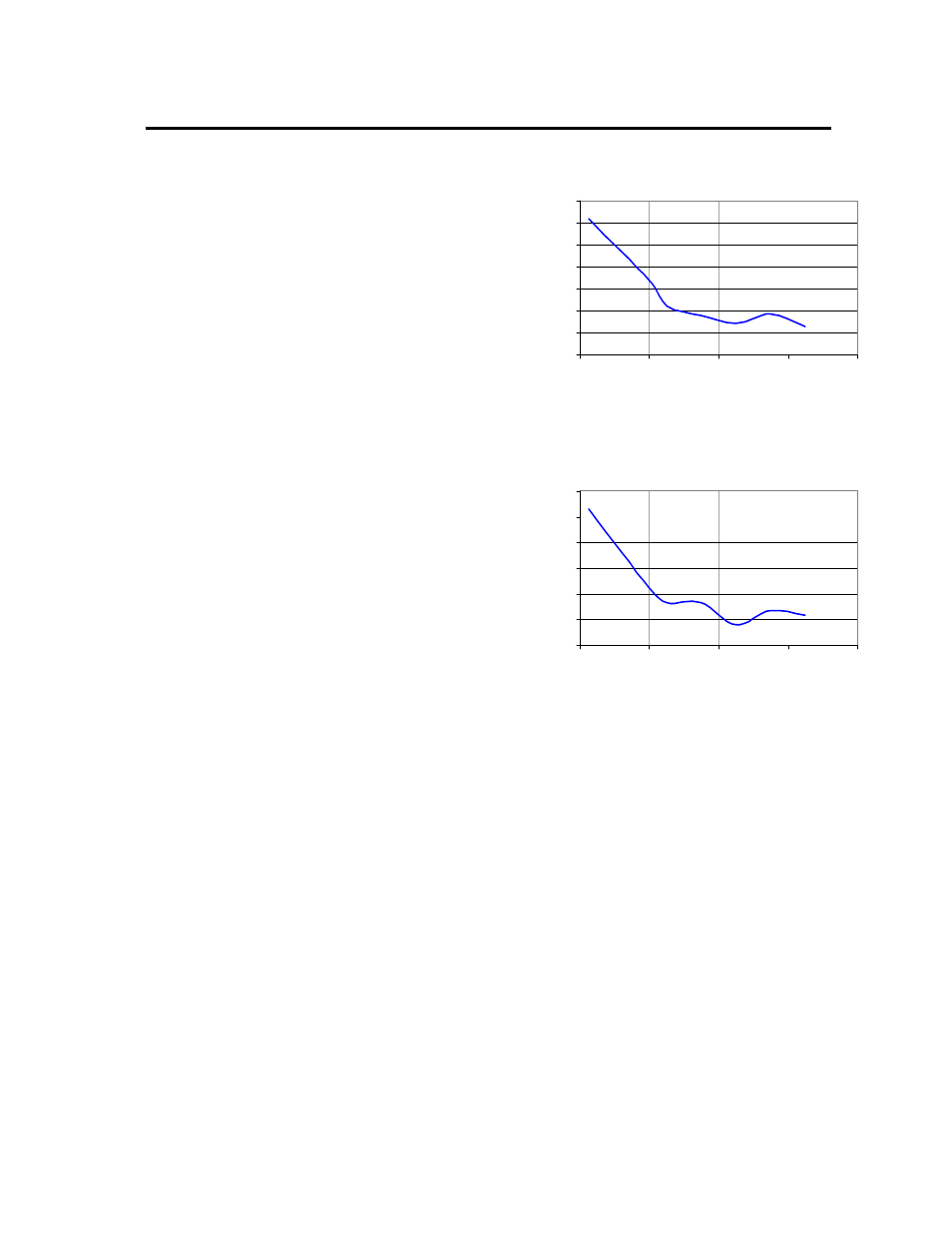
To minimize input voltage ripple, low-ESR polymer and
ceramic capacitors are recommended at the input of the
module. Figure 18 shows the input ripple voltage (mVp-
p) for various outputs with 2x150 µF polymer capacitors
(Panasonic p/n: EEFUE0J151R, Sanyo p/n: 6TPE150M)
in parallel with 2 x 47 µF ceramic capacitor (Panasonic
p/n: ECJ-5YB0J476M, Taiyo- Yuden p/n:
CEJMK432BJ476MMT) at full load. Figure 19 shows the
input ripple with 4x150 µF polymer capacitors in parallel
with 4 x 47 µF ceramic capacitor at full load.
Input
R
ipple
Vol
tage (m
Vp-
p
)
60
70
80
90
100
110
120
130
0.7
1.1
1.5
1.9
2.3
Output
Voltage
(Vdc)
Figure 18. Input ripple voltage for various output
with 2x150 µF polymer and 2x47 µF ceramic
capacitors at the input (Vin=3.3V, full load)
Input
Ri
ppl
e Vol
tage (mVp-
p
)
60
70
80
90
100
110
120
0.7
1.1
1.5
1.9
2.3
Output
Voltage
(Vdc)
Figure 19. Input ripple voltage for various output
with 4x150 µF polymer and 4x47 µF ceramic
capacitors at the input (Vin=3.3V, full load).